Page 12
DPU1U SERIES
INSTALLATION & OPERATING MANUAL
P O W E R I N G T E C H N O L O G Y
Document Number: DPU1U-MAN Rev. 4
dpu1u-man-rev1-0719.indd
9.4
Output Connections.
Output connections for A and B loads are shown in Figure 11. There
are 10 sets of barrier terminal strip connections for each side, A and B. The connections
are numbered to correspond with the numbers of the front panel breakers. The upper strip
connections are from the battery through the breakers; the lower strip connections are the
returns. Side B is on the left and side A on the right, as shown.
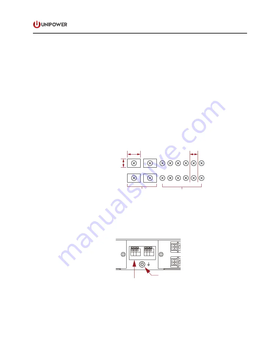
Each terminal is a no. 6-32 screw and is rated at 30 amperes. Wire sizes from no. 10 AWG
up to no. 22 AWG may be used for connections. Figure 10 below shows detailed spacing
of the terminals.
When circuit breaker distribution fitted with either 40A or 50A breakers the additional load
rating is accomodated by fitting adaptors that bridge two barrier strip terminals and provide
a single #10-32 screw. Minimum wire size for these connections is 8 AWG.
A maximum of two high current breakers is allowed.
1 2
3 4 5 6 7 8 9 10
40-50A
LOADS
#10-32
1A to 30A
LOADS
#6-32
0.75
(19.1)
0.5
(12.7)
0.378
(9.60)
Figure 11. Output Barrier Strip Detail
9.5
Form C Relay Contact Outputs.
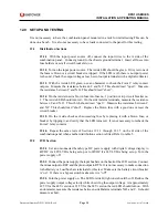
The center of the back panel has connections to the
Form C relay contact outputs for connection to external audible or visual alarm circuits.
See Figure 12.
Alarm
Contacts
Alarm LEDs
B Input
¼-20 Studs
BAT
RTN
BAT
RTN
1 2 3 4 5 6 7 8 9 10
A
B
ALARM
Ground
8-32 Stud
A Side Breakers
B Side Breakers
A Outputs
6-32 Terminal Strip
B Outputs
6-32 Terminal Strip
A Input
¼-20 Studs
BAT
RTN
BAT
RTN
1 2 3 4 5 6 7 8 9 10
B SIDE A SIDE
NO-C-NC
NO-C-NC
5
6
3
4
1
2
OFF
O
ON
I
15
OFF
O
ON
I
15
OFF
O
ON
I
15
OFF
O
ON
I
15
OFF
O
ON
I
15
OFF
O
ON
I
15
5
6
3
4
1
2
OFF
O
ON
I
15
OFF
O
ON
I
15
OFF
O
ON
I
15
OFF
O
ON
I
15
OFF
O
ON
I
15
OFF
O
ON
I
15
17.12 (434.9)
1.74
(44.2)
REAR VIEW
FRONT VIEW
Case depth: 8.94 (227.1)
2.28
(57.8)
Clear Perspex
Safety Cover
Figure 12. Alarm Contact & Ground Detail
Connection is made via two Phoenix Contact spring clamp terminal blocks. “B SIDE” is
for the Form C relay contact of side B and “A SIDE” is for the Form C relay contact of side
A. The terminals, viewed from left to right, are the normally open (NO) common (C) and
normally closed (NC) contacts, respectively. See table 5 below.


