Page 33
P O W E R I N G T E C H N O L O G Y
Manual No. PM110-6500-00 rev-2a
PM110-6500-00-rev2a-0117.indd
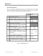
Chapter 6 Maintenance & Troubleshooting
6.1 Maintenance
Power system maintenance includes maintaining all parts of the system.
Annual maintenance should involve checking all connections on the terminals and circuit
breakers. Output voltage should be verified to be within the acceptable limits at least once a
year. Test results should be recorded and filed to see any deviations.
The power system requires periodic inspections and routine cleaning. It is very important
to keep all areas and components of the system free from dust or other unwanted objects to
ensure free air circulation and safe operation of the system.
CAUTION
To undertake any further maintenance, strictly follow all manufacturer’s
recommendations provided in the equipment manual.
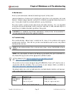
6.2 Troubleshooting
This troubleshooting chapter helps to determine the cause of the problem and suggests
possible repair solutions. If the first step of the recommendation does not solve the problem
continue to the next one.
NOTE
If the malfunctioning of the system persists, please contact UNIPOWER technical
support.
NOTE
For a description of Alarms and Messages generated by the system controller see
the Alarms/Messages section of the appropriate controller manual:
ACC Extended (ACX):
http://www.unipowerco.com/pdf/acc-man.pdf
http://www.unipowerco.com/pdf/pcc-man.pdf
The system can be remotely managed using UNIPOWER’s PowCom™ which works in
conjunction with the controller. This is covered in its own manual which is available at
http://www.unipowerco.com/pdf/powcom-man.pdf
By default, alarms are set to be indicated with a red light (higher priority) and messages
with a yellow light (lower priority).
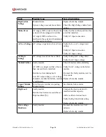
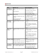
Fault
Possible Cause
Suggestion/Solution
Low System
Voltage
Module failure.
Loss of AC power.
Load exceeds module capacity.
Replace faulty module.
Verify AC input connection.
Add module to system.


