GENISYS II System Hardware Installation
UNION SWITCH & SIGNAL
SM-6900B Rev. 0.0
August 1999
2-13
2.3 PCB CONNECTOR ASSEMBLY AND CARDFILE ADDRESS SETTING
2.3.1 General
NOTE
REFER TO SECTION 3 FOR GENISYS II PRINTED CIRCUIT BOARD INTERFACES
TO EXTERNAL CIRCUITS.
Individual GENISYS II circuit boards are interfaced (as applicable) to external circuits using
connector/cable assemblies with a 48-pin or 96-pin female connector housing that attaches
directly to the matching connector on the applicable circuit board. All boards except the 96-pin
non-vital I/O PCB (N17061501) use the 48-pin connector. Each connector housing is secured to
the cardfile backplane with four small machine screws (see Figure 2-6). The complete
connector/cable assemblies may be assembled to order by US&S or assembled by the user.
The connector cable assemblies provide discrete wiring for all available I/O points on each PCB.
As shown in Figure 2-6, wire bundles are routed through a protective sleeve on one of the two
wiring openings of the connector housing. For most applications, the cable assemblies utilize only
one cable opening on the connector housing. However, non-vital I/O PCB (N17061501) may
need to use both openings to accommodate the full set of 32 input and 32 output wires.
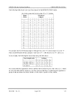
For some GENISYS II circuit boards, the connector housing also includes an Address Select PCB
with 6 two-position jumpers used to set the cardfile electrical address of the associated board.
These addresses are defined in the GENISYS II application logic (refer to Section 2.4.3). The
jumper settings must exactly match the values set in the application program to ensure normal
system operation. The following circuit boards do not require a cardfile bus address and do not
have a jumper included with the connector housing:
CPU board
Power supply
US&S provides stickers with each GENISYS II system that depict individual connector jumpers.
After each jumper connector has been set, affix a sticker to the cardfile frame directly below the
connector. Use a pen or indelible marker to mark each jumper position on the sticker.
An EEPROM is included within the special connector housing used for the CPU board. This chip
holds site-specific configuration data and allows the CPU to be changed while keeping the chip
programming intact.
2.3.2 Connector/Cable Assembly Construction Notes
User assembly of the GENISYS II connector/cable requires the following parts and tools:
Содержание GENISYS II
Страница 4: ......
Страница 6: ...GENISYS II System Hardware Installation UNION SWITCH SIGNAL 1 2 August 1999 SM 6900B Rev 0 0 ...
Страница 12: ...UNION SWITCH SIGNAL GENISYS II System Hardware Installation 2 ii August 1999 SM 6900B Rev 0 0 ...
Страница 38: ...UNION SWITCH SIGNAL GENISYS II System Hardware Installation 2 26 August 1999 SM 6900B Rev 0 0 ...
Страница 40: ...UNION SWITCH SIGNAL GENISYS II System Hardware Installation 3 ii August 1999 SM 6900B Rev 0 0 ...
Страница 60: ...UNION SWITCH SIGNAL GENISYS II System Hardware Installation 3 20 August 1999 SM 6900B Rev 0 0 ...
Страница 62: ...UNION SWITCH SIGNAL GENISYS II System Hardware Installation 4 ii August 1999 SM 6900B Rev 0 0 ...
Страница 66: ...UNION SWITCH SIGNAL GENISYS II System Hardware Installation 4 4 August 1999 SM 6900B Rev 0 0 ...
Страница 67: ......


