background image

Introduction      

      Rear Panel      Set Up      Speakon Assembly      Operating Modes      Protection      Features      Specifications

Front Panel

DSP-4000 FRONT PANEL 

page 3

Figure


1

1. Rack Mounting Ears - 

Two front panel mounting holes are provided on 

each mounting ear.

2. Fan Inlet Grills and Filter - 

DSP-4000 amplifier is cooled by two rear-

mounted fans. Cool air from front grills is filtered and flows over the 
heatsinks and exhausts to back side. Make sure these outlets remain 
clear to allow unrestricted air flow.

3. AC Power Switch - 

DSP-4000 amplifier has a front-panel AC mains 

power switch.

4. Gain Control - 

This rotary knob is used to control the output signal of 

the channel. Tuning the knob in clockwise direction will increase output 
signal level.

5. Control Buttons for adjusting the DSP software - 

These control 

buttons are used to adjust functions when connect the amplifier to the 
control computer. The required functions can be set-up via its exclusive 
control software.

6. Protect Indicator - 

The red protect LED will begin to glow when the 

channel goes into protect mode. When the channel goes into protect 
mode, all output for the channel will turn off.  This is to protect any 
speakers connected to the channel.

7. Signal Indicators - 

These green LED's will glow according to the 

average signal output.

8. Limiter Indicator - 

DSP-4000 comes with a built-in limiter for each 

channel. The limiter reduces the average input level when the signal 
begins to distort, this process is designed to reduce distortion and 
protect the speakers.When the input signal overloads, the white LED 
will glow which indicates it's a signal overload situation.

9. Clip Indicator - 

This red LED will begin to flash when the channel 

begins to overload (clip), at this point the channel will begin to distort. 
Under heavy clipping activity, lower the channel's gain control to reduce 
the risk of damage to your speakers and amplifier. This LED may glow 
when the unit has been turned off, this is normal.

10. LCD Display - 

This LCD display is available to control all the related 

functions when connect this unit with computer. Please see amplifier 
features for more information.

UNiKA

 DSP-4000

ENTER

ESC

UTIL

EDIT

Limiter

0 dB

-3 dB

-6 dB

LEVEL A

LEVEL B

NAV/PM1

PM2

Protect

Protect

Clip

1

3

9

7

5

1

3

9

7

5

UNiK A

P R O F E S S I O N A L   AU D I O

DSP

0

4

0

0

1

2

3

4

5

6 7 8 9 10

Содержание DSP Series

Страница 1: ...ing the proper and safe operation of your new amplifier DSP Series DSP 4000 Made in Taiwan Professional Power Amplifiers Index 02 Introduction 03 Front Panel 04 Rear Panel 5 Set Up 0 07 Speakon Assembly 08 Operating Modes 12 Protection 13 Features 14 Specifications UNiKA ...

Страница 2: ...avertissements supplémentaries situés dans le guide Ce symbole est utilisé pour indiquer à l utilisateur qu il trouvera d importantes instructions importantes sur l utilisation et l entretien de l appareil dans la littérature accompagnant le produit Dieses Symobl soll den Anwender vor unisollierten gefährlichen Spannungen innerhalb des Gehäuses warnen die von Ausreichender Stärke sind um einen ele...

Страница 3: ...ower supply cord or the plug has been damaged B Objects have fallen or liquid has been spilled into the unit C The appliance has been exposed to rain or water D The fixture does not appear to operate normally or exhibits a marked change in performance Congratulations and thank you for purchasing DSP 4000 amplifier This amplifier is representation of UNiKA s continuing commitment to produce the bes...

Страница 4: ...e channel goes into protect mode all output for the channel will turn off This is to protect any speakers connected to the channel 7 Signal Indicators These green LED s will glow according to the average signal output 8 Limiter Indicator DSP 4000 comes with a built in limiter for each channel The limiter reduces the average input level when the signal begins to distort this process is designed to ...

Страница 5: ...e unused connectors may be used for loop through connection to other amplifiers TRS pin setting Tip signal positive Ring signal negative Sleeve ground XLR pin setting Pin 2 signal positive Pin 3 signal negative Pin 1 ground 15 Channel 1 2 XLR THRU Jack These jacks are used to send a parallel signal from the channel 1 or 2 input jack to another device or amplifier 16 Reset Button This button is use...

Страница 6: ...a XLR cable to the input of channel one You may now connect a XLR cable from the channel one Input Thru jack to the input jack of another amplifier s channel one input This will reduce the use of Y cables OUTPUTS BINDING POST BANANA PLUG Connect your speakers to the binding post outputs on the rear of the amplifier The speaker wire may be connected by bare wire directly connected usually for perma...

Страница 7: ...ctions will run between the two positive red leads Use channel two positive output terminal for the speaker s negative connection and the channel one positive output terminal for the speaker s positive connection Typical speaker output using bare wire Insert bare wire into the binding post and tighten Typical speaker output using spade connectors Insert bare wire into the binding post and tighten ...

Страница 8: ... to properly match the positive and negative leads of each wire Figure 13 5 Slide the connector insert B into the connector housing A making sure that the large notch on the outer edge of the insert lines up with the large groove on the inside of the connector housing The insert should slide easily through the housing and out the other side until it extends approximately 3 4 inch from the end of t...

Страница 9: ... Be sure your amplifier and all other audio equipment are powered down Flip the Parallel Stereo Mono Bridge switch to the Mono Bridge position Connect input signal to channel one Connect your speaker across the red output binding post on the rear of your amplifier Turn your equipment on your amplifier should always be the last item you turn on Apply an input source signal to your amplifier Use the...

Страница 10: ...00 PROTECTION LIMITER The DSP 4000 amplifier comes with a built in limiter When the input signal overloads the CLIP LED indicates a signal overload at this time the volume should be lowered to reduce distortion If the input gain level is not reduced the built in limiter will activate During signal overload the limiter will reduce the input audio signal enough to minimize the amount of clipping A l...

Страница 11: ...ns such as EQ LPF HPF Limiter Delay and digital signal input via the front panel LCD display and can be adjusted when connect it to computer with its exclusive control software THRU THRU will allow the user to daisy chain one amplifier s signal input into another amplifier Plug the signal source outputs into the first amplifier s input patch from the amplifier s THRU jacks to the next amplifier s ...

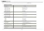
Страница 12: ...0W RMS Stereo 800W RMS Stereo 3750W RMS 2100W RMS Total Harmonic Distortion 20Hz 20kHz rated output power 8 ohms Less than 0 01 Input Sensitivity and Impedance rated output power 8 ohms 1 02V RMS 0 dBv 5 25 13 3cm 19 48 3cm 16 40 64cm 70 5 lbs 32kg Dimensions Weight Height Width Depth Weight Frequency Response 10 Hz 40 kHz 20 Hz 20 kHz Power Consumption rated output power 8 ohms 20A 0 220V c a 50H...

Страница 13: ...page 12 Introduction Front Panel Rear Panel Set Up Speakon Assembly Operating Modes Protection Features Specifications UNiKA DSP 4000 ...

Страница 14: ...Professional Power Amplifiers UNiKA ...

Отзывы: