


PART II: INSTALLATION
21
ELECTRICAL CONNECTIONS
To execute the electrical connections, proceed as follows:
1
remove the cover from the electrical board, unscrewing the fixing screws;
2
execute the electrical connections to the supply terminal board as shown in the attached wiring diagrams;
3
check the direction of the fan motor (see next paragraph);
4
refit the panel cover.
NOTE: the burners are supplied for three-phase 380/400/415/480 V supply, and in the case of three-phase 220/230/240 V sup-
ply it is necessary to modify the electrical connections into the terminal box of the electric motor and replace the overload
tripped relay.
Note on electrical supply
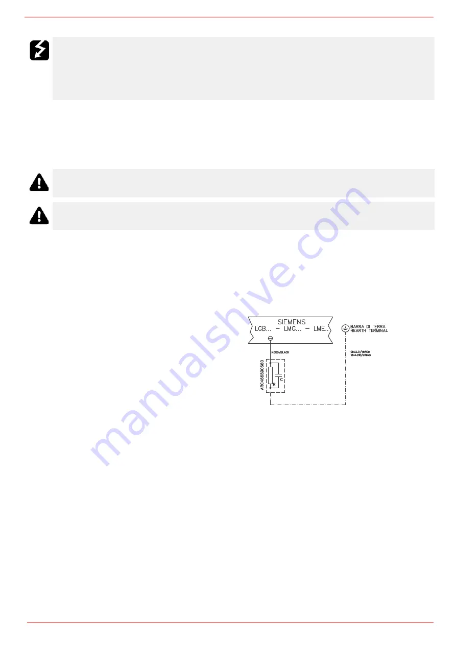
In the case where the power supply of the AUXILIARIES of the phase-phase burner (without a neutral), for the flame detection it is
necessary to connect the RC circuit Siemens between the terminal 2 (terminal X3-04-4 in case of LMV2x, LMV3x, LMV5x, LME7x) of
the base and the earth terminal, RC466890660. For LMV5 control box, please refer to the clabeling recommendations avaible on the
Siemens CD attached to the burner
WARNING! Respect the basic safety rules. make sure of the connection to the earthing system. do not reverse
the phase and neutral connections. fit a differential thermal magnet switch adequate for connection to the mains.
WARNING! before executing the electrical connections, pay attention to turn the plant’s switch to OFF and be
sure that the burner’s main switch is in 0 position (OFF) too. Read carefully the chapter “WARNINGS”, and the
“Electrical connections” section.
ATTENTION: Connecting electrical supply wires to the burner teminal block MA, be sure that the ground wire is
longer than phase and neutral ones.
WARNING: (only for double stage and progressive burners) The burner is provided with an electrical bridge
between terminals 6 and 7; when connecting the high/low flame thermostat, remove this bridge before connecting
the thermostat.
CAUTION: check the motor thermal cut-out adjustment
LMV2/3... - LMV5...
M
Key
C - Capacitor (22 nF , 250 V)
LME / LMV - Siemens control box
R - Resistor (1 M
Ω
)
M: Terminal 2 (LGB, LME), Terminal X3-04-4 ( LMV2x, LMV3x,
LMV5, LME7x)
RC466890660 - RC Siemens filter
Содержание RX1025.1
Страница 41: ......
Страница 42: ......
Страница 43: ......
Страница 45: ...User manual Siemens LMV 5x M12914CA Rev 0 03 2008...
Страница 46: ......
Страница 57: ......
Страница 58: ......
Страница 59: ......
Страница 62: ...Annex1 Example for motor cable...
Страница 63: ......
Страница 64: ...Annex 2 Example for sensor cable...
Страница 65: ......
Страница 66: ......
Страница 70: ......