


PART II: INSTALLATION
9
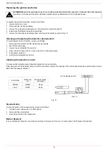
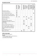
Matching the burner to the boiler
The burners described in this manual have been tested with combustion chambers that comply with EN676 regulation and whose
dimensions are described in the diagram . In case the burner must be coupled with boilers with a combustion chamber smaller in
diameter or shorter than those described in the diagram, please contact the supplier, to verify that a correct matching is possible, with
respect of the application involved. To correctly match the burner to the boiler verify the type of the blast tube . Verify the necessary
input and the pressure in combustion chamber are included in the burner performance curve; otherwise the choice of the burner must
be revised consulting the burner manufacturer. To choose the blast tube lenght follow the instructions of the boiler manufacturer. In
absence of these consider the following:
Cast-iron boilers, three pass flue boilers (with the first pass in the rear part): the blast tube must protrude no more than
Dist
= 100
mm into the combustion chamber. (Fig. 5)
Pressurised boilers with flame reversal: in this case the blast tube must penetrate
Dm
50 ÷ 100 mm into combustion chamber in
respect to the tube bundle plate.(Fig. 6)
The length of the blast tubes does not always allow this requirement to be met, and thus it may be necessary to use a suitably-sized
spacer to move the burner backwards or to design a blast tube tha suites the utilisation (please, contact the manifacturer).
Fig. 5
Fig. 6
Fig. 7
Key
a) Heat output in kW
b) Lenght of the flame tube in meters
c) Flame tube firing intensity in MW/m
3
d) Combustion chamber diameter (m)
Fig. 7 - Firing intensity, diameter and lenght of the test flame tube as a function of the
heat input in kW.
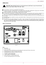
SIDE UP
SIDE
DOWN
Dist
Dm