


PART II: INSTALLATION
5
MOUNTING AND CONNECTING THE BURNER
How to interpret the burner’s “Performance curve”
To check if the burner is suitable for the boiler to which it must be installled, the following parameters are needed:
furnace input, in kW or kcal/h (kW = kcal/h / 860);
backpressure (data are available on the boiler’s ID plate or in the user’s manual).
Example:
Furnace input: 600kW
Backpressure: 4mbar
In the “Performance curve” diagram (Fig. 4), draw a vertical line matching the furnace input value and an horizontal line matching the
backpressure value. The burner is suitable if the intersection point A is inside the performance curve.
Fig. 4
Data are referred to standard conditions: atmospheric pressure at 1013mbar, ambient temperature at 15°C.
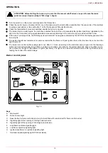
Burner model identification
Burners are identified by burner type and model. Burner model identification is described as follows.
Type
RG92
Model
G-. PR. S. *.
A.
(1)
(2)
(3)
(4)
(5)
(6)
(1) BURNER TYPE
RG91, RG92
(2) FUEL
G -
Light oil
(3) OPERATION (Available versions)
AB - Double stage
(4) BLAST TUBE
S -
standard
L -
extended
(5) DESTINATION COUNTRY
* - see data plate*
(6) BURNER VERSION
A -
Standard
PART II: INSTALLATION
Campo di lavoro bruciatori
Tipo P60 Mod. M-xx.x.IT.A.0.50 - M-.xx.x.IT.A.0.65
-1
0
1
2
3
4
5
6
7
8
100
200
300
400
500
600
700
800
900
Potenza kW
Contropressione in camera di
combustione mbar
A