


PART III: MAINTENANCE
22
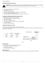
Replacing the ignition electrodes
To replace the ignition electrodes, proceed as follows:
1
remove the burner cover;
2
disconnect the electrodes cables;
3
remove the combustion head (see par. “Removing the combustion head”);
4
loose screw that fasten the ignition electrodes;
5
remove the electrodes and replace them, referring to the values quoted on Fig. 12.
Cleaning and replacing the detection photoresistor
To clean/replace the photoresistor, proceed as follows:
1
disconnect the system from the electrical power supply;
2
shut off the fuel supply;
3
remove the photoresistor from its slot;
4
clean it using a clean cloth; do not use any burner cleansing sprays;
5
if necessary, replace it;
6
insert the photoresistor into its slot.
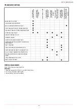
Checking the detection current
To measure the detection signal follow the diagram on the next picture.
If the signal is not in the advised range, check the electrical contacts, the cleaning of the combustion head, the position of the photore-
sistor and if necessary replace it.
Fig. 14
Seasonal stop
To stop the burner in the seasonal stop, proceed as follows:
1
turn the burner main switch to 0 (Off position)
2
disconnect the power mains
3
close the fuel valve of the supply line
Burner disposal
In case of disposal, follow the instructions according to the laws in force in your country about the “Disposal of materials”.
ATTENTION:
avoid
the electrodes to get in touch with metallic parts (blast tube, head, etc.), otherwise the boiler operation
would be compromised. Check the electrodes position after any intervention on the combustion head.
Fig. 13
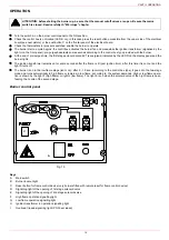
Control box
Flame sen-
sor
Minimum detec-
tion signal
LMO44
QRB4
45
μ
A
LAL2..
QRB1
95
μ
A
34 35
+
MC TERMINAL BLOCK
-