


PART III: MAINTENANCE
20
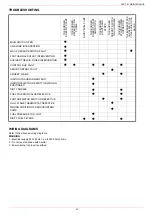
At least once a year carry out the maintenance operations listed below. In the case of seasonal servicing, it is recommended to carry
out the maintenance at the end of each heating season; in the case of continuous operation the maintenance is carried out every 6
months.
ROUTINE MAINTENANCE
Check and clean the cartdrige of the fuel filter, replace it if necessary (see next paragraph);
carefully check the fuel flexible hoses for leaks;
check and clean the filter on the fuel pump: bilter must be thoroughly cleaned at least once in a season to ensure correct working of
the fuel unit. To remove the filter, unscrew the four screws on the cover. When reassemble, make sure that the filter is mounted
with the feet toward the pump body. If the gasket between cover and pump housing should be damaged, it must be replaced;
remove, check and clean the combustion head (page 32); when reassembling, carefully observe the measures on page 21;
check the ignition electrodes and their ceramic insulators, clean, adjust and replace if necessary page 33;
remove and clean the oil nozzles (IMPORTANT: do not clean the nozzles using metallic or sharp utensils, use only solvents or
steam); at the end of maintenance operations, refit the burner, turn it on and check the combustion. If in doubt, replace the defec-
tive nozzle/s. In case of intensive use of the burner, the nozzles must be replaced at the end of the working season;
check and carefully clean the flame detection photoresistor, if necessary replace it and, if in doubt, check the detection current fol-
lowing the scheme in Fig. 30;
clean and grease levers and rotating parts.
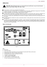
1 Close the bowl valve before the self cleaning filter
2 Switch off any electrical equipment on board on the filter (example motorization or heaters)
3 Disconnect the outlet pipe from the cover of the self cleaning filter
4 Remove the cover with all the filter pack, leaving only the bowl on the line
5 Clean any residue on the bottom of the bowl and clean the seat of the O-ring seal
6 Insert the filter pack again making sure to respect the correct inlet/outlet direction or any references on the cover and tray
7 Replace the filter by following the reverse order operations
8 Make sure there is no leakage and give the power to any electrical equipmente on the filter
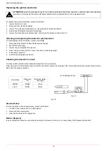
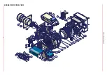
Removing the combustion head and the oil gun
1
Remove the top cover
C
;
2
remove the photoresistor from its seat;
3
unscrew the revolving connectors (
E
in figure) on the fuel pipes (use 2 spanners to avoid loosening the connections attached to the
distributor block);
4
loosen
VRT
screw to free the threaded rod
AR
, then screw out the 2 screws
V
holding the washer
R
and the screw
VRT
again;
5
remove the whole assembly as shown in figure;
6
clean the combustion head and the oil gun by means of a vacuum cleaner; to scrape off the scale use a metallic brush.
Note: to replace the combustion head reverse the procedure described above.
WARNING: ALL OPERATIONS ON THE BURNER MUST BE CARRIED OUT WITH THE MAINS DISCONNECTED
AND THE FUEL MANAUL CUTOFF VALVES CLOSED!
ATTENTION: READ CAREFULLY THE “WARNINGS” CHAPTER AT THE BEGINNIG OF THIS MANUAL.
Thecnical procedure of self cleaning filters substitution (valid for all models)
WARNING! Drain the system by unscrewing the drain screw on the bottom of the self cleaning filter
WARNING! Replace the O-ring seal between the bowl and cover
PART III: MAINTENANCE