


PART II: INSTALLATION
10
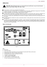
OIL TRAIN CONNECTIONS
Hydraulic diagrams for light oil supplying circuits
NOTE:
in plants where gravity or ring feed systems are provided, install an automatic interception device (see n. 4 - Fig. 8).
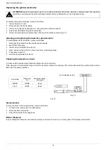
Diesel filters
1
3
2
Key
1 Manual valve
2 Light oil filter
3 Light oil feeding pump
4 One way valve
5 Flexible hoses
6 Relief valve
NOTE:
in plants where gravity or ring feed systems are provided,
install an automatic interception device.
RING CIRCUIT
GRAVITY CIRCUIT
SUCTION CIRCUIT
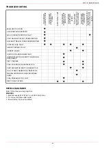
Item
Note
Connection
Max. operating
pressure
Max. operating
temperature
Filtering
degree
Protec-
tion
5
20151PE (*)
-
3/8”
1 bar
-20, 60 °C
100
μ
-
6
20201PL (*)
-
3/8”
1 bar
-20, 60 °C
100
μ
-
7
GA70501
-
1”
4 bar
90 °C
100
μ
IP65
(*) Supplied per pilot diesel fuel if present