


5
GENERAL FEATURES
This series represents monobloc gas burners made in die-cast aluminium housing, the combustion head position can be adjuste-
dwhich allows a good performance.
Fig. 1
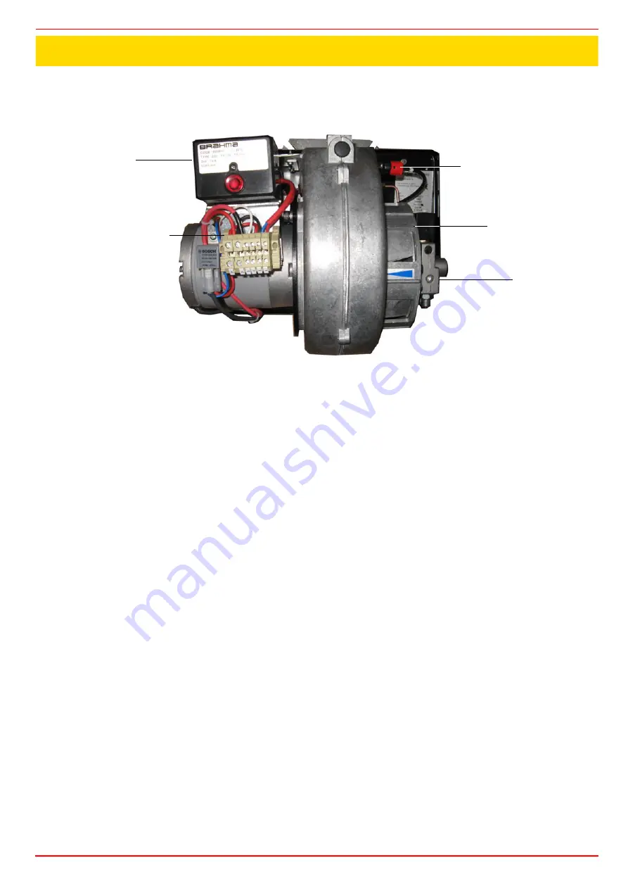
1
Gas valve group
2
Blast tube-Combustion head ass.y
3
Burner flange
4
Burner cover
The fuel coming from the supply line, is pushed by the pump to the nozzle and then into the combustion chamber, where the mixture
between fuel and air takes place and consequently the flame.
In the burners, the mixture bertween fuel and air, to perform clean and efficient combustion, is activated by atomisation of oil into very
small particles. This process is achieved making pressurised oil passing through the nozzle.
The pump main function is to transfer oil from the tank to the nozzle in the desired quantity and pressure. To adjust this pressure,
pumps are provided with a pressure regulator (except for some models for which a separate regulating valve is provided). Other pumps
are provided with two pressure regulators: one for the high and one for low pressure (in double-stage systems with one nozzle).
The adjustable combustion head can improve the burner performance. The combustion head determines the energetic quality and the
geometry of the flame. Fuel and comburent are routed into separated ways as far as the zone of flame generation (combustion cham-
ber).
How to interpret the burner “Performance curve”
To check if the burner is suitable for the boiler to which it must be installled, the following parameters are needed:
furnace input, in kW or kcal/h (kW = kcal/h / 860);
backpressure (data are available on the boiler’s ID plate or in the user’s manual).
Example:
Furnace input: 600kW
Backpressure: 4mbar
In the “Performance curve” diagram (Fig. 1), draw a vertical line matching the furnace input value and an horizontal line matching the
backpressure value. The burner is suitable if the intersection point A is inside the performance curve.
PART I: INSTALLATION
4
2
1
3
5