


UM980eb User Manual
16
Debug Support
UC-08-M32 EN R1.0
U1B
UM980
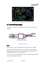
Figure 6-3 UM980 Pads (Y1-Y52) and Socket Mounting Holes (X1-X8)
7
Debug Support
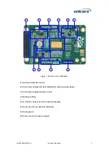
As mentioned above, TP1 and TP9 can be used to connect an external power to supply
VCCIN and V_BCKP and to measure the supply voltage and current.
TP2, TP3, TP5 and TP7 are used for internal debugging, of which TP5 and TP7 can be
used to debug I
2
C.
J1 is used for MMCX connection. After soldering the MMCX connector, it can be used to
measure the PPS signals.
J2, J3, J6 and J7 are debug ports. Connect the signal that needs to be tested to the
square hole and test the round hole, or connect the round hole to a measuring
instrument. Using these debug ports can avoid damage to the PCB pads and traces,
which is convenient for debugging.
Содержание UM980eb
Страница 25: ...Assembly Top of UM980eb...
Страница 26: ...UM980eb User Manual Assembly Bottom of UM980eb...