


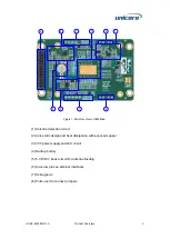


UM980eb User Manual
8
Power Supply
UC-08-M32 EN R1.0
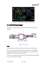
When using the LDO to power the module, you should consider the power dissipation of
the LDO.
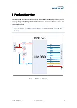
3.2
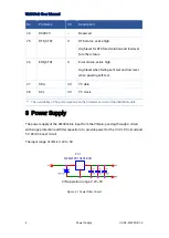
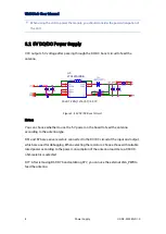
5V DC/DC Power Supply
VCC outputs 5 V voltage after passing through the DC/DC boost circuit to feed the
antenna.
Vout=1.225*(1+16/5.1)=5.07V
U5
LT3467AIDDB
Figure 3-4 5V DC/DC Boost Circuit
Notes:
You can choose whether to use the 5 V power on the board to feed the antenna
according to the antenna type.
R61 and R76 are series resistors connected to the DC/DC circuit at the input and output,
which are used for debugging. When selecting the resistors, choose those with suitable
rated power according to the power consumption of the antenna load. Here, a 0603 0-
ohm resistor is selected.
R77: After removing R61/R76 and soldering R77, you can use the external LNA_PWR to
feed the antenna.
Содержание UM980eb
Страница 25: ...Assembly Top of UM980eb...
Страница 26: ...UM980eb User Manual Assembly Bottom of UM980eb...