background image

7

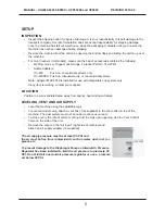
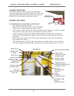
must be inserted through the lid of the left (wash) pail. Models with a Manual Rinse feature have 
another tube which needs to be inserted through the lid of the right (rinse) pail.

• 

Move the pails into the cabinet and re-connect the Suction Pipe of the left pail to the Drain Valve.

For Units Where Pails are Included (see below and next page)

SOLVENT PAIL SETUP (continued)

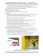
For Units Where Pails are Included (see picture on previous page)

PLASTIC PAILS 

• 

Disconnect the Suction Pipe (if not already disconnected) from the Drain Valve (make sure it is in 
the closed, horizontal, position) by pressing the button and pulling down.

• 

Bring out PAIL NO.2 and remove the Suction Pipe (and Manual Wash Suction Tube if there is 
one).

• 

Bring out PAIL NO. 1 and remove the Caps from both pails.

•   Fill PAIL NO. 2 with 3 about Gal (11 L) of clean solvent.   

• 

Fill PAIL NO. 1 with 5 about Gal (19 L) of clean solvent (about 1“ below the overflow pipe).

• 

Re-install the Caps onto the pails (the one with the tube goes on PAIL NO. 2).

• 

Put PAIL NO. 1 and the Riser back into the cabinet.

• 

Re-insert the Suction Pipe (and Manual Wash Suction Tube if there is one) into PAIL NO. 2

• 

Put PAIL NO. 2 back into the cabinet and re-insert the Overflow Pipe.

• 

Re-connect the Suction Pipe to the Drain Valve by pressing the button and pushing up.

• 

Turn the Drain Valve handle to the open position (vertical) and close the Door. 

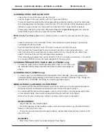
METAL PAILS - OPTIONAL (see picture below)

• 

Place two pails in front of the unit with the labels facing you and remove caps from both pails.

• 

Pour 5 Gal (19 L) of solvent into Rinse Solvent Pail and 3 Gal (11 L) into Wash Solvent Pail.

• 

Turn Handle of Drain Valve to closed (horizontal) position and disconnect the Suction Pipe (if not 
already disconnected) by pressing the button and pulling down.

• 

Bring Rinse Pump and, if present, Manual Wash Suction Tube to outside of Base Cabinet.

• 

Insert the Suction Pipe into the Wash Pail and the Rinse Pump into the Rinse Pail.

• 

If present, insert Manual Wash Suction Tube into the hole of Rinse Solvent Pail.

SOLVENT PAIL SETUP - METAL PAILS

MANUAL - UG4000-6000 UPP6500E and UP6000    

REVISION 2014-09

Содержание UG4000 Series

Страница 1: ...OPERATING MANUAL SPRAY GUN CLEANERS UG4000 UG6000 SERIES PRESSURE POT CLEANER UPP6500E PAINT CAN CLEANER UP6000 UNI RAM CORPORATION ONTARIO CANADA REV 2014 09...

Страница 2: ...8 OPERATION PRE CLEAN 8 CLEANING SPRAY GUNS AND CUPS 8 USING THE MANUAL WASH and MANUAL RINSE FEATURES 9 ADDITIONAL FEATURES UG6000 SERIES 9 HOSE CLEANING 10 AFTER CLEANING 10 DAILY MAINTENANCE FILTER...

Страница 3: ...Cautions and Warnings and on labels attached to the machine Ensure that the manual is readily available for the operator at all times If you have any questions about the operation of this machine call...

Страница 4: ...RINSE FOOT PEDAL UG4000DAM UG4000DVT UG4000 DVM UG4000E UG6000 VENT CONTROL UPP6500E TANK MANUAL WASH FOOT PEDAL UG6000 SERIES UG4500 BRUSH ON OFF BRUSH FLOW CONTROL UG4000FS UP6000 TANK BRUSH CONTROL...

Страница 5: ...f any item is missing contact your supplier LOCATION Position in a well ventilated area away from sparks heat and open flames LEVELING VENT AND AIR SUPPLY Level the machine using the adjustable legs F...

Страница 6: ...Inside the cabinet you will see two pipes strapped together the Suction Pipe and the Rinse Pump Cut the strap holding them together Do not cut the other straps holding the black and blue tubes Discon...

Страница 7: ...ils the one with the tube goes on PAIL NO 2 Put PAIL NO 1 and the Riser back into the cabinet Re insert the Suction Pipe and Manual Wash Suction Tube if there is one into PAIL NO 2 Put PAIL NO 2 back...

Страница 8: ...cycle is limited to 100 cc to minimize consumption This quanti ty is usually sufficient to clean the inside passages of the spray guns CLEANING PRESSURE POTS AND LIDS UPP6500E only To clean the pressu...

Страница 9: ...o discharge static electricity To work properly all three must be installed correctly Connect the ground wire at the back of the cabinet to an external grounded object On some models ground wires are...

Страница 10: ...ashing away paint particles with clean sol vent Replace the filter pad when damaged or when solvent cannot drain Inspect the screen located below the filter pad and clean when necessary REPLACING SOLV...

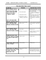
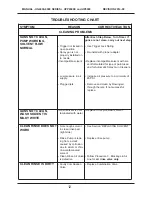
Страница 11: ...s pump to stall Follow Procedure 2 Blockage in Air Passage in Diaphragm Pump WASH SOLVENT DOES NOT FLOW AND PUMP DOES NOT MAKE A SOUND Pump leaks Blockage in air passage Replace pump Follow Procedure...

Страница 12: ...paint used and for Automatic Spray Gun Cleaners Increase air pressure to a minimum of 85 PSI Remove and clean by blowing air through the jets If not successful replace GUNS NOT CLEAN WASH SOLVENT IS M...

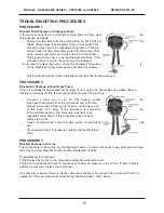
Страница 13: ...ar the blockage Connect a blow gun to an 85 PSI source Locate the blue hose that extends from the air exhaust port of the dia phragm pump Use a blow gun to blow air into the open end of this hose Turn...

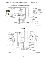
Страница 14: ...MANUAL UG4000 6000 SERIES UPP6500E and UP6000 REVISION 2014 09 14 FLOW DIAGRAMS Use the diagrams to trace the flow of compressed air and solvent UG4000DVM D E VENTED MODELS ONLY...

Страница 15: ...15 UG6000E UG4500DV UG6000EH UPP6500E MANUAL UG4000 6000 SERIES UPP6500E and UP6000 REVISION 2014 09...

Страница 16: ...REEN 10 171 TANK DRAIN VALVE 120 318 HANDLE 140 271 SUCTION TUBE ON MANUAL RINSE UNITS 140 271 SUCTION TUBE ON MANUAL WASH UNITS 100 750 PEDAL ASSY FOOT SWITCH 115 400BF AIR VALVE ASSY 140 500F SUCTIO...

Страница 17: ...80 3530 Nozzle Adapter Disposable Cup Systems Only 100 413F Paint Cap Holder 115 200 K Mechanical Timer Assembly 5 minutes 140 230 Air Passage Plug 140 2340 Trigger Clamp Plug Kit 140 340S Rotating Sp...

Страница 18: ...e for the return of your original pump Conditions of Warranty As Uni ram Corporation has no control over the working conditions or circumstances under which the purchaser stores handles or uses the pr...

Отзывы: