


Chapter 4: Performance Testing
00.053.205, Revision A SonixMDP/SP/OP Service Manual
4-2
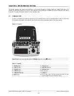
Table 4-2: Console Operation
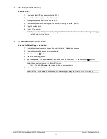
4.2
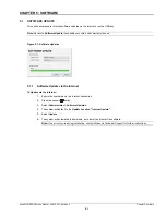
IMAGE TEST
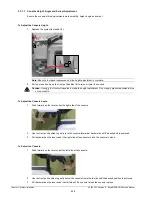
To Conduct an Image Test:
1.
Connect each of the different transducers available and press the console button.
2.
Verify that the image scanned has all elements present. Note any black static line(s) that are visible on the
image.
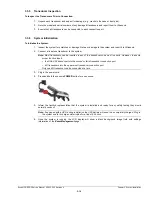
3.
If found, test with the other transducers to verify the non-visible element(s) is in the same location.
4.
Try different transducer connectors to eliminate the possibility of a malfunctioning transducer.
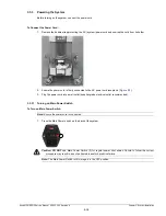
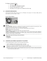
4.3
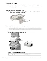
REMOVABLE (PERIPHERAL) HARDWARE (IF APPLICABLE)
The system supports many different types of removable hardware other than what comes with the system as a default
package. The following comprises a list of the supported removable hardware:
• medical grade USB printer
• medical grade footswitch (dual or triple)
• barcode reader (MDP/SP)
• USB media (memory stick, external hard drive, etc.).
• extra (HDMI-compatible) LCD display (
Console/Touch Screen Button/Dial
Expected Response
Press the console button once.
The
QSonix
page will appear on both the touch screen and the LCD display.
Note:
Press again to exit
QSonix
.
Press the console
button, then .
The LCD display will move to
M-Mode
imaging.
Press the console
button. Tap
Clarity
on
the touch screen and turn the associated dial.
The
Clarity
reading on the LCD display will move through the available settings as
the dial is turned (
Off
,
Low
,
Med
,
High
and
Max
).
Press the console button.
The button will change from blue to orange and the touch screen will display
Cine
options.
Note:
Look for the
red
Record
button on the touch screen.
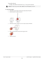
Note:
Most transducers can be inserted in any of the transducer connection ports. However, to ensure proper
function insert:
• the SA4-2/24 transducer into the second or third transducer connection port
• 4D transducers into the first (upper-most) transducer connection port.
Only one 4D transducer can be connected at a time.
Caution:
DO NOT plug the extra (HDMI-compatible) LCD display into the peripheral receptacle (
). Refer to
for instructions on connecting/installing the removable (peripheral) hardware.
M
B
B
Содержание Sonix MDP
Страница 1: ...Analogic Ultrasound Service Manual SonixMDP SP OPQ Ultrasound System...
Страница 2: ......
Страница 4: ......
Страница 14: ...Chapter 2 System Specifications 00 053 205 Revision A SonixMDP SP OP Service Manual 2 2...
Страница 46: ...Chapter 5 Software 00 053 205 Revision A SonixMDP SP OP Service Manual 5 4...
Страница 120: ...Chapter 8 DICOM 00 053 205 Revision A SonixMDP SP OP Service Manual 8 24...
Страница 147: ......


