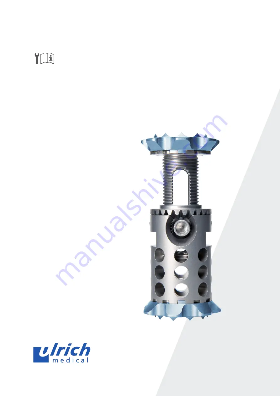
obelisc
™
vertebral body replacement
Assembly and disassembly instructions
with special cleaning instructions
Страница 1: ...obelisc vertebral body replacement Assembly and disassembly instructions with special cleaning instructions...
Страница 2: ...er to guarantee the processing and storage The product descriptions in the component overview are listed in English according to the labeling on the instruments The user must ensure that the current v...
Страница 3: ...sembly and disassembly instructions obelisc Assembly and disassembly instructions for CS 2931 XX obelisc Assembly and disassembly instructions for CS 2931G obelisc Assembly and disassembly instruction...
Страница 4: ...2931 03 Locking rod length 450 mm 6 CS 2931 08 Locking rod length 360 mm 7 CS 2931 04 Turning knob Warning The products CS 2931 01 or 06 and CS 2931 02 or 07 and CS 2931 03 or 08 each constitute an i...
Страница 5: ...inserter CS 2931 01 or 06 is pushed over CS 2931 02 or 07 CS 2931 04 is attached to the back of CS 2931 02 or 07 At the same time CS 2931 02 or 07 should be held from the front Then CS 2931 03 or 08 i...
Страница 6: ...tray Disassembling the inserter CS 2931 03 or 08 is pulled backwards out of CS 2931 01 or 06 CS 2931 04 is pulled off of CS 2931 02 or 07 At the same time CS 2931 02 or 07 should be held from the fro...
Страница 7: ...ally it must be checked whether there is any visible soiling If this is the case the previous steps must be repeated Inserter maintenance For their maintenance movable parts such as joints hinges and...
Страница 8: ...sembly and disassembly instructions for CS 2931G Components involved No Product no Product description 1 CS 2931 10 Holder curved length 450 mm 2 CS 2931 11 Expansion rod flexible length 450 mm 3 CS 2...
Страница 9: ...2931 10 curved 1 CS 2931 04 is attached to the back of CS 2931 11 2 and then CS 2931 12 is inserted 3 The instrument is now fully assembled 4 Disassembly instructions CS 2931 12 is pulled backwards o...
Страница 10: ...nd thoroughly The flexible part of CS 2931 12 must be rinsed at the rinse holes with a disposable syringe Visual inspection Finally it must be checked whether there is any visible soiling If this is t...
Страница 11: ...ng Position CS 2931 10 at an angle by placing the handle on a tray Position CS 2931 11 at an angle by placing the instrument on the tray from the flexible part General In addition the general cleaning...
Страница 12: ...belisc Assembly and disassembly instructions for CS 2932 X Components involved No Product no Product description 1 CS 2932 1 Handle for screwdriver hex 3 5 mm 2 CS 2932 2 Shaft for screwdriver hex 3 5...
Страница 13: ...e CS 2932 X CS 2932 2 or 3 is inserted into CS 2932 1 until it clicks into place Check that the grip is secure Disassembly instructions The screwdriver for locking screw must be disassembled for clean...
Страница 14: ...ll lumens and cavities must be rinsed out carefully and thoroughly Visual inspection Finally it must be checked whether there is any visible soiling If this is the case the previous steps must be repe...
Страница 15: ...15 obelisc Assembly and disassembly instructions Notes...
Страница 16: ...or and patented ulrich GmbH Co KG l Buchbrunnenweg 12 l 89081 Ulm l Germany Telephone 49 0 731 9654 0 l Fax 49 0 731 9654 2705 spine ulrichmedical com l www ulrichmedical com WS 2985 EN01_153908_R01...