Installation and Maintenance Manual
(Dr. No. 31851/b 29/05/2020)
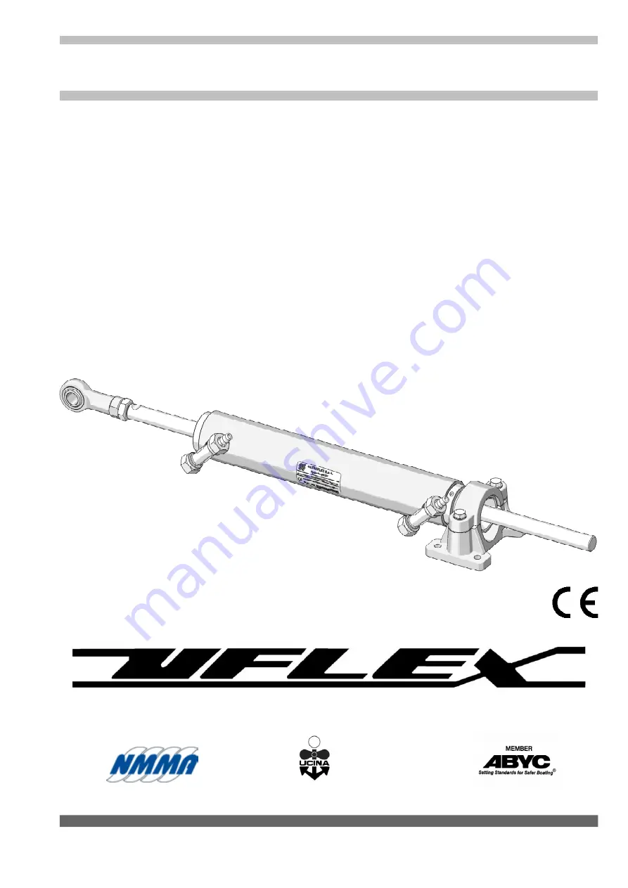
HYDRAULIC CYLINDERS FOR
INBOARD ENGINES
UC 69-I
UC 116-I
UC 168-I
UC 215-I
UC 293-I
PARTNER
Страница 1: ...InstallationandMaintenanceManual Dr No 31851 b 29 05 2020 HYDRAULIC CYLINDERS FOR INBOARD ENGINES UC 69 I UC 116 I UC 168 I UC 215 I UC 293 I PARTNER...
Страница 2: ...manufacturing capabilities in Sarasota Florida UFLEX USA can support all sectors of the marine industry regardless of volume and or product requirements And as an affliate of the ULTRAFLEX Group UFLEX...
Страница 3: ...NTENANCE 21 5 2 TROUBLESHOOTING 21 SECTION3 INSTALLATION 3 1 NECESSARY TOOLS 11 3 2 CYLINDER INSTALLATION 11 3 3 HOSE INSTALLATION 13 3 4 TYPE OF INSTALLATION 14 3 5 FILLING AND PURGING 16 3 5 1 SINGL...
Страница 4: ...mmediate hazards which CAUSE severe personal injury or death WARNING CAUTION The symbol aside indicates all the operations which must be carried out by qualified or skilled staff in order to avoid haz...
Страница 5: ...ssed or implied including not in a restricted way the suitability warranty for any special purpose Nothing contained in this manual can be interpreted as a modification or confirmation of the terms of...
Страница 6: ...ire agreements between UFLEX USA Inc and Purchaser and suspersedes all prior agreements discussions negotiations commitments and representations whether oral or written between them regarding UFLEX US...
Страница 7: ...d with a valve which prevents outgoing fluid from returning along the same hose allow the operation of the steering systems with two or more steering stations The cylinders are double acting and may b...
Страница 8: ...ng bracket Rod 1 2 3 4 2 1 4 3 5 5 A C B D E The cylinder thrust indicated is theoretical calculated with a system pressure as shown in the table This thrust does not correspond to the one generally u...
Страница 9: ...angle Installation height at the end of stroke 150 mm 30 130 mm 5 12 420 Nm 210 Nm 6 30 133 mm 5 22 429 Nm 215 Nm 130 mm 35 106 mm 4 18 343 Nm 172 Nm 5 36 102 mm 4 03 331 Nm 166 Nm 180 mm 30 156 mm 6...
Страница 10: ...ment check that the product has not been damaged during transport Also make sure that all the standard components are in the packaging see list In case of damage notify the claim to the forwarder and...
Страница 11: ...and the following loss of boat control NOTICE 3INSTALLATION 3 1Necessarytools To choose the arm according to the type of application used see paragraph 1 6 NOTICE Torque wrench Open end wrench 10 mm...
Страница 12: ...mm wrench for bolt and nut M6 UC 69 I or of 25 Nm with a 13 mm wrench for bolt and nut M8 UC 116 I 168 I 215 I 293 I NOTICE The oil fittings must be always in high position 4 Connect the joint 3 to th...
Страница 13: ...of the ball joints is not hindered DANGER CAUTION x A B y Check if the cylinder and not the helm moves up to the end stroke Minimum radius 250 mm Afterinstallingthecylinderafine adjustmentcanbecarried...
Страница 14: ...he pump must be always connected to the fitting of the side port P while the hose which is connected to the starboard side S of the pump must be connected to the fitting of the starboard side S 2 l 1...
Страница 15: ...2S 6 kit OB 6 l l 4 T fittings with bleed valves 5 tie bar 6 kit OB 2S 7 kit OB l l 7 l l 3 4 4 S P S P S P DUAL STATION SINGLE CYLINDER WITH DUAL HELM DUAL STATION SINGLE CYLINDER 1 2 3 4 l l l l l 6...
Страница 16: ...roducts throughout time The special mix of anti wear and stabilizing components of OIL15 allow ensuring great results as far as the product duration and performances are concerned in several environme...
Страница 17: ...es When the oil comes out of the bleed valve without air bubbles close the bleed valve and continue to turn the steering wheel in the same direction to fill the cylinder chamber picture 3 During this...
Страница 18: ...sly described Wait until the oil reaches the lower tank and both tanks are filled Follow the same bleeding procedure described in paragraph 3 5 1 starting from the lower station and repeat it for the...
Страница 19: ...NG 3 5 4Dualsteeringstation dualcylinder Manually unscrew the two bleed valves on the cylinder T fittings and push the cylinders to one side up to the end of stroke Position the oil bottle near the ma...
Страница 20: ...disassemble the hydraulic connections before bleeding the oil in the system completely The hoses can contain high pressure oil DANGER WARNING During installation inspection or maintenance IT IS STRIC...
Страница 21: ...in up position Look for and remove the restriction WARNING WARNING 5 1Ordinarymaintenance 5MAINTENANCE Poor installation and maintenance may result in loss of steering and cause property damage and or...
Страница 22: ...epeat the bleeding procedure as explained in this manual Repeat the filling and bleeding procedure of the system Look for the leak and contact specialized staff Oil leak Mount the helm with the fillin...
Страница 23: ...steering system is put out of service it is necessary to follow some rules in order to respect the environment Sheaths pipelines plastic or non metallic components must be disassembled and disposed o...
Страница 24: ...UFLEX USA Sarasota FL 34243 6442 Parkland Drive...
Страница 25: ...uflexusa com www uflexusa com All inboard cylinders can use standard KIT OB only if used with UFLEX UP Series hydraulic pumps whose pressure relief valve max pressure is set at 70bar 1000PSI while th...