Hardware Installation Guide
S9701-82DC
Core/Edge Router
R1.0
Страница 1: ...Hardware Installation Guide S9701 82DC Core Edge Router R1 0...
Страница 2: ...12 7 Installing Power Supply Units 13 8 Grounding the Router 15 9 Connecting Power 17 DC Version 17 AC Version 20 10 Verifying System Operation 21 Front Panel LED 21 PSU FRU LED 22 Fan FRU LED 22 11...
Страница 3: ...vides a more flexible solution for network operators With 25GE and 100GE services ports the S9701 82DC platform can enable multiple application architectures required for high traffic loading in a 5G...
Страница 4: ...ow wire for grounding Crimping tool Wire stripping tool All illustrations within this document are for reference purposes only Actual objects may differ PC with terminal emulation software Refer to th...
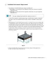
Страница 5: ...rcuit Space Clearance The S9701 82DC chassis width is 17 16 inches 43 6cm and is shipped with an adjustable mounting rail kit suited for standard 19 inch 48 3cm wide racks The depth of the S9701 82DC...
Страница 6: ...2 Installation spacing requirement S9701 82DC chassis spacing requires a height of 2RU 3 45 8 8cm a width of 19 48 3cm and a depth of 36 inches 91 4cm Thermal requirement S9701 82DC working temperatur...
Страница 7: ...k Washers 1 set 0 01lbs 2 6g 1 set 4 Micro USB Cable 3 28 1m 1 pcs 0 05lbs 24 4g 1 pcs 5 RJ45 to DB9 Female Cable 8 2 4m 1 pcs 0 27lbs 123 9g 1 pcs 6 USB 3 0 7 8 20cm 1 pcs 0 03lbs 16g 1 pcs 7 Adjusta...
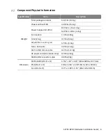
Страница 8: ...PSU 2 65lbs 1 2kg Fan module 1 10lbs 498g Ground lug 0 15lbs 66 2g Adjustable mounting rail 6 79lbs 3 1kg Micro USB cable 0 05lbs 24 4g RJ45 to DB9 Female cable 0 27lbs 123 9g AC power cord AC versio...
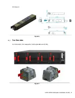
Страница 9: ...82DC Hardware Installation Guide 7 4 Identifying Your System S9701 82DC Overview Figure 4 PSU Overview Power supply unit PSU with 1 1 Redundancy Hot swappable field replaceable unit FRU AC Version Fig...
Страница 10: ...S9701 82DC Hardware Installation Guide 8 DC Version Figure 6 Fan Overview 3 1 Redundant hot swappable field replaceable unit FRU Figure 7...
Страница 11: ...E 64 75 QSFP28 Up to 6 2mi 10km 40GE 100GE 0 5 QSFP DD Up to 100m 400GE The service ports labelled in yellow and green in figure below are ethernet packet based ports used to connect to servers and ot...
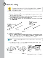
Страница 12: ...rom the outer rail The white tab is located on the inner rail 1 3 Once the inner rail is separated push the tab located on the outer rail to unlock and slide the middle rail back Figure 9 2 Install th...
Страница 13: ...hen the bracket is secured onto the rack Figure 11 4 Insert the Chassis to complete the installation 4 1 Pull the middle rail fully extended into lock position an audible click can be heard when the m...
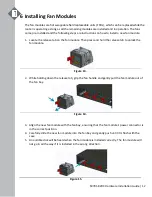
Страница 14: ...an module Then press and hold the release tab to unlock the fan module Figure 13 2 While holding down the release tab grip the fan handle and gently pull the fan module out of the fan bay Figure 14 3...
Страница 15: ...power input for AC power supply is only 110V there will only be 1000 watts per power supply and will not be enough power for the power supply to be changed while the router is in operation In order fo...
Страница 16: ...PSU s power connector is in the correct position 4 Carefully slide the new PSU into the power bay and gently push until it is flush with the case 5 An audible click will be heard when the PSU is inst...
Страница 17: ...ug onto the case This equipment must be grounded Do not defeat the ground conductor or operate the equipment without correctly grounding the equipment If there is any uncertainty about the integrity o...
Страница 18: ...for securing the grounding lug which is located on the rear of the router and remove the protective label Figure 20 6 Using 2 M4 screws and 4 washers provided with the package contents firmly lock the...
Страница 19: ...not provided must be attached to a one hole lug before connecting to the PSU The following instructions are for connecting the DC Power Cable to the lug 2 1 Strip the insulation from a DC Power Cable...
Страница 20: ...er any exposed metal on the DC power cable and lug Figure 23 2 6 Use a heat source to secure the heat shrink tubing in place Allow the heat shrink tubing to cool before attaching the DC power cable An...
Страница 21: ...ecure and may cause malfunctions If the torque is too much the terminal block or lug may be damaged Secure the plastic cover back onto the terminal block The figure below depicts how it should look on...
Страница 22: ...nector 3 Feed AC power into the system The PSU will immediately output 12V 5VSB to the system with a 110V 220V AC power source The PSU has a built in 15 amperes fast acting fuse based on the PSU maxim...
Страница 23: ...onization to external reference GNSS 1PPS PTP etc Solid Amber System timing clock synchronization is in free run or holdover mode SYS OFF No power Solid Green Host CPU BMC is up Blinking Green Reserve...
Страница 24: ...supply firmware updating Boot loader mode Red Power supply critical event causing a shutdown failure over current short circuit over voltage fan failure and or over temperature Blinking Red 1 sec Inp...
Страница 25: ...e can be connected either with the RJ45 IOIO port or the micro USB port If connecting with micro USB drivers will need to be installed To connect the console using the RJ45 IOIO port locate the port l...
Страница 26: ...HyperTerminal Windows PC Putty or TeraTerm and configure the application The following settings are for a Windows environment other operating systems may vary Baud rate 115200 bps Data bits 8 Parity...
Страница 27: ...port female connector located on the front panel of the router The USB port is a maintenance port Figure 30 Connecting a Cable to the TOD Interface 1 Connect one end of a straight through Ethernet cab...
Страница 28: ...0 ohms to the port marked GNSS ANT located on the front panel of the router Figure 32 Connecting the 1PPS Interface Connect an external 1PPS cable with an impedance of 50 ohms to the port labelled 1PP...
Страница 29: ...ze the cables For easier management label each fiber optic cable and record its respective connection Maintain a clear line of sight to the port LEDs by routing the cables away from the LEDs Before co...
Страница 30: ...upport it without compromising stability Otherwise personal injury and or equipment damage may result Caution This unit must be installed indoors The unit AC power supplies DC power supplies and its c...
Страница 31: ...o frequency energy and if not installed in accordance with the operator s manual may cause harmful interference to radio communications Operation of this equipment in a residential area is likely to c...
Страница 32: ...ch trouble occurs the user may be required to take corrective actions Installation Location Statement It is recommended that the device be installed only in a server room or computer room where access...
Страница 33: ...www ufispace com www ufispace com...