background image

Lite6 User Manual-Software Section

1. UFACTORY Studio

UFACTORY Studio is a graphical user application for controlling the

robotic arm. With this application, you can set parameters, move the

robotic arm in live control, and create a motion trajectory by simply

drag and drop the code blocks of Blockly. UFACTORY Studio allows users to

plan the motion trajectory for the robotic arm without programming skills.

You can access

UFACTORY

Studio through a browser.

UFACTORY

Studio is now

compatible with browsers: Google Chrome/ Firefox / Safari /Microsoft Edge (Chromium

kernel)

1.1 Hardware Preparation

Before using UFACTORY Studio, you must ensure that the hardware is

installed correctly and all the protective measures for the workplace

Содержание LITE 6

Страница 1: ...V 1 11 0...

Страница 2: ...1 Hardware Installation Manual 17 1 1 The Hardware Composition of the robot 17 1 2 Robot Installation 19 1 3 Power Supply for the Robotic Arm 24 2 Electrical Interface 27 2 1 Electrical Alarms and Ca...

Страница 3: ...eporting and Handling 141 1 1 Joints Error Message and Error Handling 141 1 2 Control Box Error Code and Error Handling 143 1 4 Python SDK Error Code Error Handling 146 Appendix2 Technical Specificati...

Страница 4: ...1 7 Maximum Speed 161 1 8 Specifications 162 Appendix7 Kinematic and Dynamic Parameters of UFACTORY Lite 6 163...

Страница 5: ...x1 Lite 6 Quick Start Guide x1 Main Contents of the Manual Lite6 User Manual Hardware Section 1 Lite6 hardware installation 2 Electrical interface 3 Lite6 end effector Lite6 User Manual Software Sect...

Страница 6: ...ates the position of the center of mass of the TCP relative to the default tool coordinate system with unit of mm TCP Offset Tool Center Point Offset Set the relative offset between the default tool c...

Страница 7: ...ion is the rotation direction 3 If you want to express reverse rotation invert the rotation axis vector x y z and the value of phi remains unchanged 4 Using phi and x y z can also derive the attitude...

Страница 8: ...nsitivity level and the less the force required to drag the joint in the manual mode Collision Sensitivity The collision sensitivity range is from 0 to 5 level When it is set to 0 it means that collis...

Страница 9: ...by the system In this situation the specified speed parameter is the maximum linear speed range from 0 500mm s 2 When the expected TCP motion only changes the attitude roll pitch yaw with position x...

Страница 10: ...ions Introduction This chapter contains essential safety information integrators and users must follow the instructions and pay special attention to the content with warning signs Due to the complexit...

Страница 11: ...recautions include but are not limited to Making a risk assessment for the complete system Make sure to have a safe distance between people and the robot when interacting with the robot Interfacing ot...

Страница 12: ...ould result in personal injury or damage to the equipment CAUTION If not avoided could result in personal injury or damage to the equipment Safety Precautions Overview This section contains some gener...

Страница 13: ...other device systems 5 Preliminary testing and inspection for both robotic arm and peripheral protection system before production is essential 6 The operator must be trained to guarantee a correct ope...

Страница 14: ...sure the robotic arm s joints and tools are installed properly and safely and check the status for all circuits 2 Make sure that there is enough space for the manipulator to move freely 3 Make sure th...

Страница 15: ...the safety of operators 1 Each operator who uses the robotic arm system should read the product user manual carefully Users should fully understand the standardized operating procedures with the robo...

Страница 16: ...fast 6 Be careful about dropping items that can be caused by accidental power off or unstable clamping of the robotic arm...

Страница 17: ...rm Figure 2 1 Power Adapter Figure 2 2 Emergency Stop Button Figure 2 3 The Lite 6 robotic arm system consists of a base and rotary joints and each joint represents a degree of freedom From the bottom...

Страница 18: ...the posture of the robotic arm will slightly brake and fall The emergency stop button is shown below Power off press the emergency stop button to power off the robot and the power indicator will go ou...

Страница 19: ...the full torsion of the base joint and at least 5 times the weight of the arm 1 The robotic arm and its hardware composition must not be in direct contact with the liquid and should not be placed in...

Страница 20: ...nsion of the links The figure below shows the dimensions and working range of the robotic arm When installing the robotic arm make sure the range of motion of the robotic arm is taken into account so...

Страница 21: ...2 2 Robot Installation The robotic arm has five M5 bolts provided and can be mounted through four 5 5 holes in the base of the robotic arm It is recommended to tighten these bolts with a torque of 20...

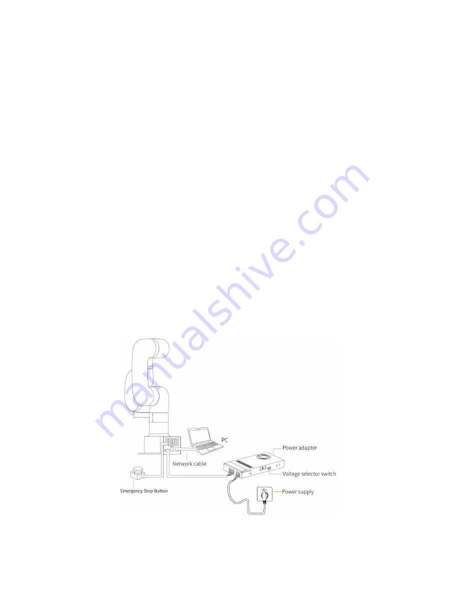
Страница 22: ...Arm Power Supply into the interface of the Robotic Arm The connector is a fool proof design Please do not unplug and plug it violently 1 2 2 4 Connect the network cable Plug the network cable into the...

Страница 23: ...fferent sizes can be mounted If the effector does not have a positioning hole the orientation of the end effector must be documented in a file format to avoid errors and unexpected results when re ins...

Страница 24: ...tion by dropping a part unexpectedly 4 Pay attention to the operation specifications of sharp end effector tools 5 If the installed end effector exceeds the robotic arm mounting surface at the zero po...

Страница 25: ...r indicator ROBOT PWR will on 2 Use the UFACTORY Studio or SDK commands to complete the operation of enabling the robotic arm 1 3 3 Shut Down the Robot 1 Press the emergency stop button 2 Go to UFACTO...

Страница 26: ...Shutdown 3 Unplug the socket...

Страница 27: ...ath due to an invalid safety stop function 1 Make sure that all the non waterproof equipment is kept dry If water enters the product turn off the power supply and contact your supplier 2 Use only the...

Страница 28: ...ology Co Ltd is not responsible for any loss caused by EMC problems 2 The length of the I O cable that used to connect the Control Box with other mechanical and plant equipment must not exceed 30 mete...

Страница 29: ...to the following table Pin sequence Color Signal 1 Brown 24V Power 2 White 0V GND 3 Green RS485 A Analog Input 0 T AI 0 4 Yellow RS485 B Analog Input 1 T AI 1 5 Black Tool Output 0 TO 0 6 Grey Tool Ou...

Страница 30: ...ctor open drain The electrical specifications are as follows Parameter Min Typical Max Unit Open circuit Voltage 0 5 30 V Voltage when sinking 50mA 0 05 0 20 V Sink Current 0 100 mA Current through GN...

Страница 31: ...as follows Parameter Min Typical Max Unit Input Voltage 0 5 30 V Logic Low Voltage 1 0 V Logic High Voltage 1 6 V Input Resistance 47k 2 2 2 1 Tool Digital Input Usage The following figure shows the c...

Страница 32: ...t 2 In current mode the pull down resistance depends on the range of the input current 2 2 3 1 Non differential Analog Input The following figures show how the analog sensor can be connected to a non...

Страница 33: ...ow to connect devices to the electrical I O of the robot The I Os are extremely flexible and can be used in many different devices including pneumatic relays PLCs and emergency stop buttons The figure...

Страница 34: ...Yes Configurable Function CO0 CO7 General Output Yes Motion Stopped Yes Robot Moving Yes Warning Yes Collision Yes Manual Mode Yes Reduced Mode Yes Offline Task Running Yes Robot Enabled Yes Emergency...

Страница 35: ...in 24V Power Supply PWR GND Voltage 23 24 30 V PWR GND Current 0 1 8 A External 24V Input Requirement 24V 0V Voltage 20 24 30 V 24V 0V Current 0 3 A The digital I O electrical specifications are as f...

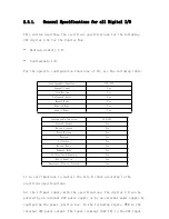
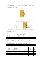
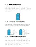
Страница 36: ...I O failure should not result in the loss of safety features There are two fixed safety inputs The robotic arm emergency stop input is only used for the emergency stop of the device The protective sto...

Страница 37: ...ost applications one or more additional emergency stop buttons are required The figure below shows how to connect one or more emergency stop buttons 2 3 2 3 Share Emergency Stop with other Machines Wh...

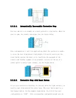
Страница 38: ...the reset button outside the door as to reactivate the movement of the robotic arm Another example of an automatic recovery is the use of a safety pad or a safety laser scanner see the figure below 2...

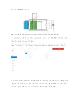
Страница 39: ...reset in UFACTORY Studio The specific steps are as follows Enter Settings I O Input Configure CI0 as safeguard reset Save 2 If the robot needs to resume motion connect SI0 and SI1 to GND and trigger...

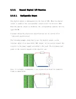
Страница 40: ...ctor will be open OC OD You must follow the electrical specifications set in section 2 4 1 universal specification The following example shows how to use the digital output as the internal output is a...

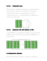
Страница 41: ...t in the 2 4 1 universal specification This example shows how a simple button is connected to a digital input 2 3 3 3 Communicate with other Machines or PLCs If general GND 0V is established and the m...

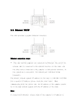
Страница 42: ...o the computer or LAN network interface If the connection is successful the network port indicator blinks frequently The default network segment IP address of the robot is 192 168 1 2 254 For a specif...

Страница 43: ...change the computer IP address to the same network segment and close the computer s network proxy To test whether the computer can communicate with the robotic arm open the command terminal and input...

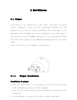
Страница 44: ...hanical claw is 22 38mm Regardless of the installation method the stroke of the gripper is only 16mm The maximum payload of the gripper 1kg There are two states of the gripper open and close 3 1 1 Gri...

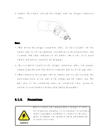
Страница 45: ...he gripper connector and the tool end effector connector must be on the same side 3 When connecting the gripper and the robotic arm be sure to align the positioning holes at the ends of the gripper an...

Страница 46: ...p firmly Indicator status When the vacuum gripper is powered on the power supply indicator near the vacuum gripper is constantly red When the vacuum gripper is on the IO status indicator is constantly...

Страница 47: ...he vacuum gripper and the robotic arm be sure to align the positioning holes on the two ends of the interface The male pins of the connecting cable are relatively thin to avoid bending the male pins d...

Страница 48: ...and drop the code blocks of Blockly UFACTORY Studio allows users to plan the motion trajectory for the robotic arm without programming skills You can access UFACTORY Studio through a browser UFACTORY...

Страница 49: ...etwork communication is normal 6 Check if the robotic arm is powered and the emergency stop button is disabled If the power indicator of the robotic arm lights up it means the power is on 1 2 Connect...

Страница 50: ...ed by wireless network the robot and router are connected by Ethernet cable Note It is not recommended because of the delay and packet loss of wireless connection 4 The robot PC and network switch are...

Страница 51: ...ipped from the factory the default IP address is 192 168 1 xxx The factory IP address of the device has been marked on the base of the robot Therefore to successfully communicate with the control box...

Страница 52: ...Step2 Open the Ethernet Step3 Open the Properties Step4 Open the IPV4...

Страница 53: ...n check whether the computer IP is within 192 168 1 2 192 168 1 255 the tail number should be 2 to 255 and can not be the same as the IP address of the control box If not please modify the computer s...

Страница 54: ...ic Arm 1 Open the browser 2 Enter in the search bar the IP address of the control box 18333 For example if the IP address of the control box is 192 168 1 80 enter 192 168 1 80 18333 in the search bar...

Страница 55: ...Sensitivity Robot Mounting and Motion Enable Robot State Error indicating that the robotic arm has not been enabled or the robot is in error state Click the blue Enable Robot button to enable it Norm...

Страница 56: ...parameters of the robotic arm upgrade the system software etc 1 3 3 Toolbar Window To adjust its size you can make a selection in the Window drop down menu or adjust the size by dragging the border o...

Страница 57: ...alue for a smooth trajectory Position step Set the step length for fine cartesian position X Y Z adjustment in Live control Attitude step Set the step length for fine adjustment of TCP orientation in...

Страница 58: ...sitivity level is and the smaller the additional torque required for the robotic arm to trigger collision protection If the load or installation direction is not set accurately it may cause false alar...

Страница 59: ...ion 3 Set the initial position of the robot in Live control OK Save the changes Cancel Cancel the changes 1 4 2 End Effector When the end effector provided in the option is installed at the end of the...

Страница 60: ...ned on the default TCP payload will be changed to the TCP payload parameter of the gripper When installing other end effectors not officially provided at the end of the robotic arm please choose other...

Страница 61: ...f the centre of gravity of payload in mm this position is expressed in default TCP coordinate located at flange center Frame B in the above figure If there is virtually no load at the end both TCP pay...

Страница 62: ...e payload of the current robotic arm and display the current payload at the top which is used for controlling the entire robotic arm and is related to the normal use of manual mode and collision detec...

Страница 63: ...entification Manually inputting can be selected if the weight of the payload and the approximate center of gravity of the payload are known The center of gravity of the payload is set based on the ini...

Страница 64: ...the new payload has been determined it cannot be changed 1 4 3 2 TCP Offset On this page the current offset of the robotic arm can be set and the additional TCP offset data can be recorded The additi...

Страница 65: ...can choose to identify its TCP offset parameter Select Select the offset data to be deleted in the next step Delete Delete the selected offset data Note the current default offset data cannot be delet...

Страница 66: ...red by low level input signals General Input The user can use the IO freely in Blockly or SDK program only when the controller input is set as a general input otherwise it will cause a function confli...

Страница 67: ...below functions can be configured for each output General Output The user can use the IO freely in Blockly or SDK program only when the controller output is set as general output otherwise it will ca...

Страница 68: ...sion When the robotic arm reports an error of collision the output is high Manual mode When the Manual Mode is turned on the output is high Offline task running When the robotic arm is running the off...

Страница 69: ...cking the button 1 4 5 Safety Settings 1 4 5 1 Safety Boundary Safety Boundary When this mode is turned on the working range of the robotic arm in Cartesian space can be limited If the tool center poi...

Страница 70: ...1 4 5 2 Reduced Mode Reduced Mode When this mode is turned on the maximum linear speed maximum joint speed and joint range of the robotic arm in Cartesian space will be limited...

Страница 71: ...and stop motion and will also result in uncontrolled motion of the robotic arm after entering manual mode The built in IMU of the robot arm will detect the direction of gravity When the deviation bet...

Страница 72: ...situation How to determine the tilt angle and rotation angle The initial position of the robotic arm On the horizontal plane when the user is facing the robotic arm side the initial position is on the...

Страница 73: ...hich is vertically mounted The direction where your four fingers point is the positive direction and vice versa The range of rotation angle 180 Make sure the robotic arm is properly placed according t...

Страница 74: ...s the angular values of orientation relative to the base coordinate system After this offset setting user coordinate system becomes the world origin instead of robot base New Create a new user coordin...

Страница 75: ...ault offset Default The data is the default current base coordinate offset Cancel Cancel the selection Save Save the modified data Discard Discard the modified data Example When expressed in coordinat...

Страница 76: ...atures Orientation Control The robot supports adjusting the rotation of the robot arm through the axis angle and R P Y Generally it is recommended to use the axis angle since the axis angle control is...

Страница 77: ...void the Blockly program from being affected by the network communication between the client and the control box during the running process which improves the running speed of the program Note After t...

Страница 78: ...u can quickly adjust parameters through the Quick access button in any interface of UFACTORY Studio Quick access You can select the parameters you want to access quickly and the selected parameters wi...

Страница 79: ...1 4 9 3 Advanced Tools Friction Identification The friction identification is only carried out with the help of technical support please do not identify by yourself Advanced Logic...

Страница 80: ...d by the stop command Collision Rebound When this mode is turned on the robotic arm will rebound backward for a certain distance after it collides with an obstacle If collision sensitivity is not zero...

Страница 81: ...voltage value of the robotic arm is 0 50V The range of the joint current value of the robotic arm is 0 35A Note When using the above functions the joint firmware version 2 7 0 2 Unlock Joints Click l...

Страница 82: ...d by the robotic arm Attention should be paid to adjusting the joint into the range manually when it exceeds the range of the joint 3 In the simulated robotic arm mode clicking the unlock joint button...

Страница 83: ...multi turn error of the robotic arm and modify the speed threshold of the robotic arm Note This function should be completed under the guidance of technical support Please contact the technical suppo...

Страница 84: ...Send after turning on the cyclic function 1 4 10 System Settings System Settings mainly include Check Update System Information Network Settings and Log Check Update Software updates for UFACTORY Stud...

Страница 85: ...obotic arm IP address firmware version SN address and software version of the robotic arm can be checked Robot controller shutdown reboot Access to robot conttroller Shutdown Access to Settings System...

Страница 86: ...ll restart After the restart action is completed the pop up window will close and the robotic arm will be automatically reconnected The operation is equivalent to the shutdown and startup process of t...

Страница 87: ...lease refer to Appendix 4 Lite6 Software Firmware Update Method 1 4 10 3 Network Settings The IP address subnet mask broadcast address and default gateway of the robot are displayed on this page You c...

Страница 88: ...been reset successfully The reset IP is 192 168 1 111 4 Please unplug the cable connecting RI0 and GND and wait for the robot to start up 60 seconds 5 Enter 192 168 1 111 18333 in the browser to conn...

Страница 89: ...at IP address you modify the IP address of the control box will be automatically changed to 192 168 1 111 so after modifying the IP Be sure to unplug the cable connecting RI0 and GND 1 4 10 4 Log The...

Страница 90: ...and check if the network connection is normal The Simulate Robot indicates that the robotic arm is connected and is currently in simulation mode In this mode only the joint motion of the simulated ro...

Страница 91: ...e and fall 1 5 3 Real Robot Simulation Robot Real Robot It can control the motion of the real robotic arm in the interface of UFACTORY Studio and the virtual robotic arm will reflect the position and...

Страница 92: ...ts of joint modules The position of the end effector is controlled by coordinating the rotation angle of each joint The joint motion reaches the target point with the fastest path the end trajectory i...

Страница 93: ...d TCP coordinate system The trajectory of tool center point in the Cartesian space is a straight line Each joint performs a more complex movement to keep the tool in a straight path The TCP path is un...

Страница 94: ...tation of the TCP coordinate system changes according to the changes of the joint angles Roll Pitch Yaw respectively rotates around X Y Z of the base coordinate system and the final TCP orientation is...

Страница 95: ...f the Roll Pitch Yaw are coinciding in the space and the valid range is 180 so it is possible to have both 180 when the robotic arm is reporting the position Roll angle pitch angle and yaw angle RPY T...

Страница 96: ...and the tool coordinate system Position Attitude Real time Display X Y Z represents the coordinates of the tool center point TCP position of the robotic arm under the base coordinate offset Roll Pitch...

Страница 97: ...Line Motion Attitude Step on the homepage Note When the real time control base coordinate system tool coordinate system is switched if the coordinate system offset is not 0 0 0 0 0 0 the user coordin...

Страница 98: ...you want the program to run at high speed you can add a speed command in the Blockly motion program Joint Operating Speed The range is 1 s 180 s When the robotic arm is in operation the actual maximum...

Страница 99: ...cement motion and the rotational motion depends on the one that takes more time but in principle it is better to separate the displacement from the rotation command 1 6 Blockly Graphical Programming B...

Страница 100: ...ect xxx Click to expand to display all created items the currently open item xxx is displayed when it folds Import Project Click to import the Blockly project from the local drive Download All Click t...

Страница 101: ...mode you can also run the Blockly motion program to observe the motion of the virtual robotic arm 1 6 2 Blockly Workspace Drag the code block into the action panel the code execution is top down user...

Страница 102: ...ank workspace of the non code block the function is mainly for all code blocks Undo Undo the previous operation Redo Restore the last undo operation Collapse Blocks Collapse all code blocks Expand Blo...

Страница 103: ...displayed in the default middle position Collapse Block Folds the code block of the current workspace Disable Block Stop the execution of the running command of the current code block The opposite is...

Страница 104: ...triggered event suitable for plc End Effector Contains common commands to control the end effector such as gripper vacuum gripper Logic Contains commonly used logic commands Loop Contains common loop...

Страница 105: ...t project refer Settings TCP Payload from the drop down list Set tcp offset X Y Z R P Y Set the end offset of the current project reference Settings TCP Offset from the drop down list Set world offset...

Страница 106: ...tion commands for successful continuous motion calculation motion With this command operators can set the state of the robotic arm movement pause stop It is used to control the state of the robotic ar...

Страница 107: ...motion relative to TCP coordinates move circle position 1 to position 2 From current position the whole circle is determined by current position and position1 and positon2 center angle specifies how...

Страница 108: ...hich can be used to acquire set and monitor IO interface operations The controller has 8 digital input interfaces 8 digital output interfaces 2 analog input interfaces and 2 analog output interfaces T...

Страница 109: ...of the specified position to be reached by the robot arm with the unit of mm The digital IO is triggered as soon as the system detects that the TCP position enters a spherical area centered at X Y Z...

Страница 110: ...n off the pump of the gripper object is picked release Detect whether the vacuum gripper has picked released the object If it is detected that the vacuum gripper has picked released the object then ju...

Страница 111: ...on and off object detection true detect whether the object is picked if not it will jump out of the entire program object detection false do not detect whether the object is picked 1 6 8 Application R...

Страница 112: ...g method of the if else sentence 1 Click the setting button on the command block then the command block will pop up a selection box as shown below 2 At this point drag the else code block to the botto...

Страница 113: ...mmand contained in the loop will be executed X times repeat while until do When the condition is not met it jumps out of the loop break Terminate the loop 1 6 11 Math You can use the above code block...

Страница 114: ...indicates the time interval the message is displayed the unit is in second the message indicates the content of the prompt message string printing Users can print the entered string below and set the...

Страница 115: ...the variable by adding or subtracting variable Rename variable Rename the variable Delete variable Delete the variable 1 6 14 Function to do something Users can define a new function without a return...

Страница 116: ...ont of the main programs 1 6 15 Set Edit Motion Coordinates Long press Move button to move the robotic arm to the position of the current command Click edit to pop up the live control interface to re...

Страница 117: ...efore there may be no solution multiple solutions approximate solutions When the solution of the Cartesian command from point A to point B is not ideal insert a third joint command between the two poi...

Страница 118: ...ython development integration environment that can directly use Python SDK API and check the Blockly projects converted into Python code Create a new project Create a new file Create a new folder Rena...

Страница 119: ...it was created Delete projects Open Open the projects and display them in the edit box Note The project folder is not available please create a new project by yourself Controller Command Caching Mech...

Страница 120: ...be discarded The commands issued should not exceed 256 command caches It is recommended to keep the number of cached sent commands under 256 all the time 1 8 Recording The position of the joint is obt...

Страница 121: ...a new recording file Manual Mode will be turned on accordingly by clicking on the button and the robotic arm can be dragged directly for trajectory recording When starting recording be sure to pay at...

Страница 122: ...Download the file Delete the file Import Project Import recorded trajectory Download All Download all current files...

Страница 123: ...sian coordinates unit mm the speed between each instruction is discontinuous Arc Linear Motion to achieve linear motion between Cartesian coordinates unit mm inserting an arc between two straight line...

Страница 124: ...tion with the fastest speed 1m s and acceleration unit mm This command has no buffer only execute the latest received target point and the user needs to enter the servoj mode to use In servoj mode the...

Страница 125: ...ssessment must be done and the operator should be cautious 2 1 2 Analysis of Robotic Arm Movement Mode 4 motion modes of the control box Python SDK set_mode Mode 0 Position control mode In this mode t...

Страница 126: ...use Before turning on the joint teaching mode be sure to confirm that the installation direction of the robotic arm and the TCP load are set correctly otherwise the arm may not be able to remain stat...

Страница 127: ...nary State 2 Standby The control box is already in motion ready state but no motion commands are cached for execution State 3 Pausing The robotic arm is set to pause state and the motion commands buff...

Страница 128: ...the acceleration of joint motion in s2 move joint J1 J2 J3 J4 J5 J6 J7 Radius Set each joint angle for the joint movement the unit is Wait true false indicates whether to wait for the execution of thi...

Страница 129: ...ngle servo_id 1 angle 45 is_radian False b If servo_id is None or 8 E g arm set_servo_angle angle 30 45 0 0 0 0 0 is_radian False speed joint speed the default unit is s Unit if is_radian True the uni...

Страница 130: ...int motion commands is a way to plan the continuous joint motion of the robotic arm Blockly The motion trajectory of the robotic arm in the above example is as follows Key parameter description Radius...

Страница 131: ...tion at the turn this speed will not be continuous between this and next motion as shown in the figure below speed will decelerate to 0 at point B before moving to C Note Radius 0 cannot realize conti...

Страница 132: ...unique once the target point is confirmed and the corresponding posture in the execution process is random X Y and Z control the position of TCP in base or tool coordinate system in the unit of mm Wh...

Страница 133: ...ue the unit is rad if is_radian False the unit is pitch attitude pitch default unit is Unit if is_radian True the unit is rad if is_radian False the unit is yaw attitude yaw default unit is Unit if is...

Страница 134: ...low 200mm s for debugging otherwise there will be a high security risk Blockly Key parameter description Radius 5 Radius 5 in the move arc line command refers to setting the radius of the transition a...

Страница 135: ...ansition at the turn this speed will not be continuous between this and next motion as shown in the figure below speed will decelerate to 0 at point B before moving to C Note Radius 0 cannot realize c...

Страница 136: ...ose 2 The calculation method of three point drawing circle Use the current point as the starting point and then set two position points Three points define a circle Make sure these three points are no...

Страница 137: ...ired posture when completing the trajectory center angle Indicates the degree of the circle When it is set to 360 a whole circle can be completed and it can be greater than or less than 360 Note To ac...

Страница 138: ...circle based on three point coordinates The three point coordinates are current starting point pose 1 pose 2 Parameter pose1 Cartesian coordinates x mm y mm z mm roll rad or pitch rad or yaw rad or p...

Страница 139: ...ed which will cause the angular velocity of some joints to be too fast leading to loss of control A common situation is that when the wrist joint the penultimate one is at or near the axis of the firs...

Страница 140: ...s speed of the joint when it passes the singularity point Therefore try to avoid the singularity point or pass the singularity point through joint motion 3 Processing method for singularity point Case...

Страница 141: ...x 2 Enable the robotic arm UFACTORY Studio enable method Click the guide button of the error pop up window Python SDK enable method Refer to Error Handling Mode ROS library Users can view related docu...

Страница 142: ...ot to move when it s powered on Please restart the robot with the Emergency Stop Button on the Control Box If multiple reboots do not work please contact technical support S17 Single turn Encoder Erro...

Страница 143: ...value in the Motion Settings Please check if the Emergency Stop Button on the Control Box is released S49 EEPROM Read and Write Error Please restart the robot with the Emergency Stop Button on the Con...

Страница 144: ...rror Please check whether gripper is installed and the baud rate setting is correct C21 Kinematic Error xArm 6 xArm 7 or Lite 6 Please re plan the path xArm 5 Please long press the Aligning the Hand o...

Страница 145: ...t The track recording duration exceeds the maximum duration limit of 5 minutes It is recommended to re record C35 Safety Boundary Limit The robot reaches the safety boundary Please let the robot work...

Страница 146: ...r s program operation Once the warning occurs the arm will set the warning flag and return it together in the command reply Otherwise no other operations will be performed The robotic arm will still o...

Страница 147: ...A32 Trajectory read write timeout A33 Playback trajectory timeout A41 Vacuum gripper wait timeout A100 Waiting for completion timeout A101 Too many failures to detect the status of the end effector A...

Страница 148: ...ility 0 2mm Max Speed of End effector 500mm s Ambient Temperature Range 0 50 C Power Consumption Min 4 8 W Max 350W Input Power Supply 24 V DC 14 5 A ISO Class Cleanroom 5 Robotic Arm Mounting Any Pro...

Страница 149: ...e same time 2 After updating please download the latest User Manual and Developer Manual from the official website to learn about the latest features of the robot The download link https www ufactory...

Страница 150: ...update using the xarm tool gui tool is as follows 1 Tool download Download address of xarm tool gui tool UFACTORY Studio and xArm Firmware installation package xArm Tool GUI Since your PC connected to...

Страница 151: ...the robot then click Connect 3 After successful connection click the Check Update button then click the Install Online in the Firmware installation box UFACTORY Studio installation box and finally cli...

Страница 152: ...e console of the xarm tool gui will display Install firmware success or Install Studio success And wait for the control box to reboot the reboot usually takes about 2 3 minutes 2 When you use the foll...

Страница 153: ...s of xarm tool gui tool UFACTORY Studio and Firmware installation package xArm Tool GUI Since your PC connected to the robot cannot access the Internet please download the above installation package u...

Страница 154: ...ne in the Firmware installation box UFACTORY Studio installation box then load the corresponding firmware or UFACTORY Studio compressed package in the folder Click the Install button After the install...

Страница 155: ...y takes about 2 3 minutes 3 When you use the following network setting methods please use UFACTORY Studio to update the UFACTORY Studio and firmware online The method of online update using UFACTORY S...

Страница 156: ...x and router are connected by ethernet Cable Click Settings on the UFACTORY Studio homepage enter System Settings Check Update click Update Wait for the system to prompt to restart and then click Rest...

Страница 157: ...rgency stop button and the robotic arm does not need to be enabled 2 Clean After the robotic arm is used for a long time there may be dirt or grease on the carbon fiber shell in rare cases a small amo...

Страница 158: ...After sales policy For the detailed after sales policy of the product see the official website 3 https www ufactory cc warranty and returns 4 The general process of after sales service is 1 Contact U...

Страница 159: ...f the product When you need to send the product back to get repaired please pack the product with the original box to protect the product during the transportation 2 If you need to send the control bo...

Страница 160: ...ials 1 3 Transport Storage and Handling Move the robot to the zero position by UFACTORY Studio then put the lite 6 robot and Control Box in the original packaging Transport the robot in the original p...

Страница 161: ...glass body cartridge fuse 1 6 Stop Categories A Stop Category 1 and a Stop Category 2 decelerates the robot with drive power on which enables the robot to stop without deviating from its current path...

Страница 162: ...150 3 3 5 300 4 360 5 124 6 360 Payload 1kg Maximum Reach 440mm Degrees of Freedom 6 Repeatability 0 2mm Maximum Joint Speed 90 s Weight robotic arm only 9kg Weight including accessories packing box...

Страница 163: ...CTORY Lite 6 Modified D H Parameters Size Parameters unit mm Joint Coordinate Definition Kinematics theta offset deg d mm alpha deg a mm Joint1 0 243 3 0 0 Joint2 90 0 90 0 Joint3 90 0 180 200 Joint4...

Страница 164: ...eters Size Parameters unit mm Joint Coordinate Definition Kinematics theta offset deg d mm alpha deg a mm Joint1 0 243 3 90 0 Joint2 90 0 180 200 Joint3 90 0 90 87 Joint4 0 227 6 90 0 Joint5 0 0 90 0...

Страница 165: ...Address 2F Building M 6 Ma Que Ling Industrial Zone Nanshan District Shenzhen Guangdong China Website www ufactory cc Dynamics Mass kg Center of Mass mm Link1 1 411 0 36 41 95 2 5 Link2 1 34 179 0 0...

Отзывы: