background image

18

1601-054

1601-054

1601-054

1601-054

1601-054

1601-054

1601-055

1601-054

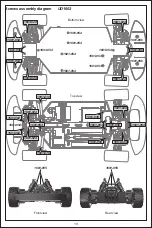
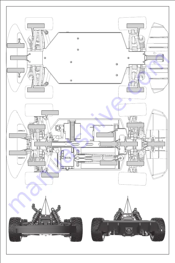
Screws assembly diagram

Bottom view

Top view

Front view

Rear view

1601-055

1601-053

1601-053

1601-054

1601-024

UD1601

1601-024

1601-024

1601-019

1601-019

1601-024

1601-024

1601-024

1601-024

1601-024

1601-054

1601-062

1601-062

1601-060

1601-056

1601-056

1601-054

1601-054

1601-056

1601-049

1601-054

Содержание UD1601

Страница 1: ...nd specifications are subject to change without notice All the information in this manual has been carefully checked to ensure accuracy if any printing errors our company reserve the final interpretation right This product is suitable for users over 14 years old Please read this instruction manual carefully befores use Operating Instructions ...

Страница 2: ...02 ...

Страница 3: ...ht The model must stop immediately and check for the reasons when it is operating abnormal Keep in mind that people around you may also operate a radio control model The motor is a heating part please do not touch it Please keep the package or instructions as they contain important information Failure to follow these instructions may result in injury to yourself or others You may also cause proper...

Страница 4: ...he model before charging 3 DO NOT charge the battery when it is bulging or expanding 4 Keep away from damp corrosive environment and heat source 5 Please charge the battery under adult supervision 6 Pay attention to the polarity of the battery when installing or replacing the battery 7 Different types of batteries or old and new batteries should not be mixed 8 DO NOT short circuit any terminals 9 ...

Страница 5: ... 1601 009 1601 010 1601 007 1601 008 Tire Motor 3mm Locknut Headlight group Body clips Front shock tower Rear shock tower Steering servo Rear bumper Battery hold down Front shock Rear shock Upper chassis Front bumper assembly 2 4GHz Integrated ESC Li ion Battery Guidance before operation Preparation of remote control model UD1601 Summary ...

Страница 6: ...1 002 Body clips 1602 008 Front shock tower 1602 008 Rear shock tower 1602 014 Rear bumper 1601 013 Battery hold down 1601 007 Steering servo 1602 009 Front shock 1602 009 Rear shock 1601 016 Upper chassis 1601 010 Front bumper assembly 1601 011 2 4GHz Integrated ESC 1601 012 Li ion Battery UD1602 Summary ...

Страница 7: ...put port and then connect other USB output ports When charging the charging indicator is flashing and the indicator is always on after charging Do not put the battery in the model when charging The battery must be cooled before charging Battery input port Li ion Battery Charger output port Charging Charger box Power USB adapter not included Please use the charging box provided with the product and...

Страница 8: ...ld down reset Clips reset The battery output port and the ESC input port are correctly connected Press for 1 second to turn on the power The lights flash and enter the frequency matching state Press for 2 second to turn off the power After the battery is assembled reset the body Put the battery in the slot ...

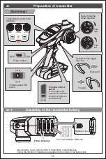
Страница 9: ...tteries Battery Cover 2 1 Preparation of transmitter Assembly of the transmitter battery Summary Power switch Transmitter function main interface Default steering wheel direction Default throttle trigger direction Backward Forward Turn right Turn left Throttle speed limit switch Car lights control button The car lights color mode can be switched and the car lights can be switched off ...

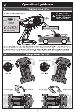
Страница 10: ...the transmitter and the red indicator light will flash quickly After the car power is turned on the transmitter and the car will carry out automatic frequency matching When the indicator light of the transmitter and the car lights are always on the frequency matching is successful In the process of frequency matching the car lights will flash rapidly At this time the gyroscope is being calibrated ...

Страница 11: ...e trigger Steering wheel Throttle trigger Steering wheel Throttle trigger Pull the throttle trigger back gently and the car will move forward slowly The throttle trigger is pulled to the maximum and thecar moves forward quickly When the car is moving forward the throttle trigger is pushed forward and the car stops moving After the throttle trigger returns to the middle position it pushes forward a...

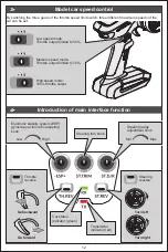
Страница 12: ...ng trim knob Throttle reverse Car status indicator green Transmitter indicator red Steering reverse Steering range adjustment knob Low Min Max High Low speed mode Throttle output limited to 50 By switching the three gears of the throttle speed limit switch three different maximum speeds of the car can be set Medium speed mode Throttle output limited to 75 High speed mode 100 throttle output ...

Страница 13: ... left and right directions of the front wheels The steering range adjustment knob can be used to adjust the left and right steering angle of the car The action ratio decreased The action ratio increases When the front wheel is left the knob rotates to the right Minimum steering angle Maximum steering angle When the front wheel is right the knob rotates to the left 1 There is no ESP function when t...

Страница 14: ...s soon as possible to avoid accidents When the signal is weak or the signal is interrupted the red indicator of the transmitter will flash quickly Please operate within the effective control distance to avoid accidents 6 5 1 Replacement of parts Low battery alarm Replace the ESC Weak signal alarm Pull out all the plugs and remove the ESC upward Replace with a new ESC Front Steering servo Li ion ba...

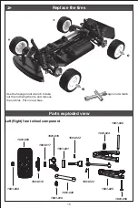
Страница 15: ...017 1601 021 1601 022 1601 023 1601 024 1601 026 1601 025 2 Left Right front wheel component Replace the tires Parts exploded view Use the hexagon nut wrench to take out the nut fixing the tire and remove the old tires Put on new tires Hexagon nut wrench 1601 050 ...

Страница 16: ...16 1601 051 1601 050 Left right rear wheel components Differential assembly 1601 004 1601 005 1601 016 1601 017 1601 018 1601 021 1601 027 1601 029 1601 029 1601 027 1601 022 1601 024 1601 026 ...

Страница 17: ...17 1601 057 1601 030 1601 030 1601 007 1601 032 1601 033 1601 024 1601 033 1601 048 1601 019 1601 009 1602 009 1601 031 1601 019 1601 024 Front rear shock absorber components Steering system components ...

Страница 18: ...embly diagram Bottom view Top view Front view Rear view 1601 055 1601 053 1601 053 1601 054 1601 024 UD1601 1601 024 1601 024 1601 019 1601 019 1601 024 1601 024 1601 024 1601 024 1601 024 1601 054 1601 062 1601 062 1601 060 1601 056 1601 056 1601 054 1601 054 1601 056 1601 049 1601 054 ...

Страница 19: ...1 019 1601 024 1601 024 1601 024 1601 024 1601 054 1601 062 1601 062 1601 060 1601 054 1601 054 1601 054 1601 054 1601 054 1601 054 Bottom view 1601 053 1601 053 1601 054 1601 024 1601 024 1601 024 1601 024 1601 054 1601 056 1601 056 1601 056 1601 056 1601 054 1601 054 1601 056 1601 049 1601 054 ...

Страница 20: ...tacles or interferences Restart the transmitter Transmitter battery low Motor reaches the effective service life Signal interference exists Encounter obstacles or interferences Potentiomer is not in the center The wheel or transmission shaft is entangled with foreign matters Long frequency matching time Operation delay The vehicle moves forward backward automatically or makes a sound of en Please ...

Страница 21: ...003 1601 004 1601 005 1601 005 1601 006 A Front Rear shock tower assembly Steering servo Rear bumper Battery hold down 1601 008 1601 007 1602 008 1601 009 1602 009 Body assembly Rear bumper Tire B Front Rear shock tower assembly Front Rear shock assembly Upper chassis Front Rear shock assembly Front bumper assembly 2 4GHz Integrated ESC Li ion Battery Buyable accessories ...

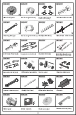
Страница 22: ...riers assembly 2 5 10mm Pivot balls Main spur gear Bulkhead tie bars front 2 5 12mm Pivot balls Differential housing Chassis Motor gear Motor mounts Steering bellcrank Suspension arms front Suspension arms rear Differential assembly Servo saver Steering linkage Ball bearing 8 4 3mm Ball bearing 12 8 3 5mm Shaft 1 8 6 8mm Shaft 2 5 32mm Shaft 2 5 21mm Metal Rear Dogbones Metal Rear Wheel shafts Met...

Страница 23: ...058 Bulkhead tie bars rear Main propeller shaft 2 13mm PM Screw pin set 2 5 16 5mm PM Screw pin set 2 5 7mm KM Screws 2 5 10mm KM Screws 2 3 8mm PB Screws 2 3 6mm PB Screws 2 3 4 5mm PB Screws 2 3 6 5mm PB Screws 2 3 8 8mm PB Screws 2 3 5 7mm PB Screws 2 10mm PB Screws 2 3 14mm PB Screws 2 5 14mm PB Screws Socket nut wrench Hex wrench 2 5 11 8mm PM Shoulder screws 2 5 5mm PM Screws Taillight group...

Страница 24: ... not occur in a particular installation If this equipment does cause harmful interference to radio or television reception which can be determined by turning the equipment off and on the user is encouraged to try to correct the interference by one or more of the following measures Reorient or relocate the receiving a ntenna Increase the separation between the equipment and receiver Connect the equ...

Отзывы: