


MAX-M5Q - Hardware Integration Manual
FTX-HW-13008
Objective Specification
Design
Page 14 of 40
3.1.2
Layout checklist
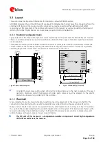
See section 3.3 for more details on the layout.
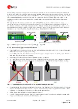
Position the GPS/GNSS module according to the recommendation.
Follow the grounding concept.
Keep the micro strip as short as possible.
Add a ground plane underneath the GPS/GNSS module to reduce interference.
For improved shielding, add as many vias as possible around the micro strip, around the serial
communication lines, underneath the GPS/GNSS module, etc.
Include appropriate EOS/ESD/EMI protection measures. This is especially important for designs including
wireless modules.
3.1.3
Antenna checklist
The total noise figure should be well below 3 dB.
If a patch antenna is the preferred antenna, choose a patch of at least 15x15x4 mm for standalone
GPS/QZSS, or choose a patch of at least 25x25x4 mm for GPS + GLONASS. For smaller antennas, an LNA
with a noise figure <2 dB is recommended.
Make sure the antenna is not located close to noisy parts of the circuitry (e.g. micro-controller or display).
To optimize performance in environments with out-of-band jamming sources, use an additional SAW
filter.
The micro strip must be 50
Ω
and be routed in a section of the PCB where minimal interference from
noise sources can be expected.
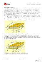
In case of a multi-layer PCB, use the thickness of the dielectric between the signal and the first GND layer
(typically the 2nd layer) for the micro strip calculation.
If the distance between the micro strip and the adjacent GND area (on the same layer) does not exceed 5
times the track width of the micro strip, use the “Coplanar Waveguide” model in AppCad to calculate
the micro strip and not the “micro strip” model. See section 4.1.4.
Use an external LNA if your design does not include an active antenna when optimal performance is
important.
For information on ESD protection for patch antennas and removable antennas, see section 6.3.3 and if
you use GPS for design in combination with GSM or other radio, then check sections 6.3.5 to 6.3.7.
For more information dealing with interference issues, see the GPS Antenna Application Note [3].
3.2
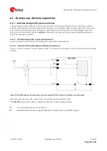
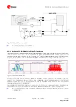
Design considerations for minimal designs
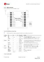
For a minimal design with the MAX-M5Q GPS/GNSS module, the following functions and pins need
consideration:
•
Connect the Power supply to
VCC
.
•
Assure an optimal ground connection to all ground pins of the module.
•
Connect the antenna to
RF_IN
over a 50
Ω
•
If you need improved startup or use AssistNow Autonomous in your application, connect a backup supply
voltage to
V_BCKP
.


