


EVK-VERA-P174 - User Guide
UBX-17048707 - R06
Getting started
Page 8 of 30
2
Getting started
The basic steps to evaluate the VERA-P1 series modules using the EVK-VERA-P174 evaluation kit
are provided below:
1.
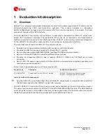
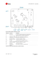
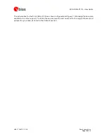
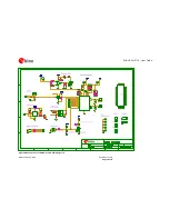
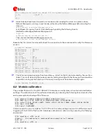
Make sure that jumpers are placed on the current measurement pin headers on the main board
as shown in Figure 2. The jumpers for 5 V, 3.3 V, and 1.8 V supply must be placed on the power
supply board to use the on-board voltage regulators. The jumper for VIO voltage selection on the
power supply board is set to 3.3 V by default. See the description on the back of the board for the
jumper locations.
Figure 2: Jumper locations on the main board
2.
Place jumpers on Boot_0 and Boot_1 to select the USB DFU boot mode.
3.
Connect two external 5.9 GHz antennas to the SMA antenna connectors of the VERA-P1 series
module.
⚠
Always make sure that the RF ports are properly terminated to a 50
Ω
load such as an antenna,
spectrum analyzer or 802.11p receiver. If you directly connect the RF ports of the two
EVK-VERA-P174 evaluation kits, include a minimum attenuation of 50 dB, to avoid damage to
the modules.
4.
Connect a 9 – 28 V, 12 W power adapter to the 2.5 x 2.5 mm barrel power connector (
) on
the power supply board. The power and reset LEDs will be on.
5.
Connect the micro USB connector on the power supply board to a host processor or a PC. The
USB LED will be on.
6.
Follow the quick start instructions in section 4.1 to build the Linux driver and applications for the
VERA-P1 series modules and download the firmware to the VERA-P1 series module.
5V
3V3
VIO
Boot
mode