
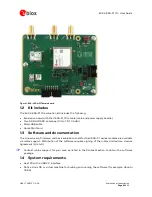


EVK-VERA-P174 - User Guide
UBX-17048707 - R06
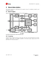
Board description
Page 14 of 30
Pin No. Pin name
Type
Level
Description
5
VIO2
Power VIO
VIO voltage
7
GND
Ground
10
1PPS
I/O
I: 1.8 - 5.5 V
O: 3.3 V
1PPS signal output from GNSS (J108 1-2) or input to VERA-P1 (J108 2-
3)
11
NEO_UART_RX I
0 - 3.3 V
GNSS UART RX
12
NEO_UART_TX O
3.3 V
GNSS UART TX
13
GND
Ground
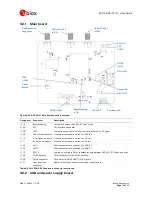
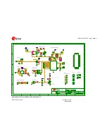
3.3.8
SMA connectors
The EVK-VERA-P174 includes two SMA connectors, ANT1 (J102) and ANT2 (J103), which are used
to connect external antennas or measurement instruments to the antenna pins of the VERA-P1
module.
A third SMA connector (J104) is included to connect an active antenna to the on-board NEO-M8U
GNSS module.
The SMA connectors on the EVK are specified for RF signals up to 18 GHz.
⚠
Always ensure that the RF ports of the VERA-P1 module are properly terminated to a 50
Ω
load
such as an antenna, spectrum analyzer, or 802.11p receiver. If you directly connect the RF ports
of two EVK-VERA-P174 evaluation kits, include a minimum attenuation of 50 dB, to avoid
damage to the modules.
3.3.9
Host interface connector
The host interface connector is used in the EVK to connect the VERA-P1 main board to the power
supply and USB interface board. Additionally, it can be used to connect the VERA-P1 main board
directly to a compatible host board. The connector on the main board is a QMS-052-0675-L-D-PC4
and the counterpart on the power supply board is a QFS-052-0675-L-D-PC4.
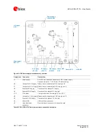
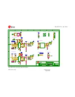
3.4
LEDs
Table 9 lists the available LEDs on the EVK-VERA-P174:
Name
Designator Location
Function
Power
LED1
Power supply board
Indicates 3.3 V supply (LED on)
USB
LED2
Power supply board
Indicates USB connection to the host (LED on)
Reset
LED103
Main board, near pin 1 of VERA-P1 Indicates VERA-P1 module in reset (LED off)
1PPS
LED102
Main board
Indicates 1PPS signal (LED blinking)
Firmware LED101
Main board
Indicates firmware loaded (LED on) through current
measurement
Table 9: LED Description
3.5
Buttons
The reset button on the main board (S101) resets the VERA-P1 module. The button on the power
supply board (S1) is used to reset the on-board power supply for the EVK.
3.6
Design files