
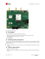


EVK-VERA-P174 - User Guide
UBX-17048707 - R06
Board description
Page 12 of 30
3.3
Connectors
3.3.1
Power supply and configuration
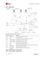
The VERA-P1 module is supplied with 3.3 V, 5 V, and a VIO that can be either 3.3 V or 1.8 V. Power
supply for the evaluation board is provided through a DC power jack connector (J1) with an input
voltage of 9-28 V.
All supply voltages can be generated from the on-board DC-DC converters and LDO regulators or
supplied externally via the connectors J5 (5 V), J4 (3.3 V) and J6 (1.8 V) of the power supply board.
Disconnect the jumpers J8, J7 or J9 on the power supply board to use the external power supply
connectors. The VIO voltage for the VERA-P1 module can be selected with jumper J10 on the power
supply board between 1.8 V and 3.3 V.
Individual current consumption on the 3.3 V, 5 V, and VIO rails of the VERA-P1 module can be
measured with the respective pin headers J109, J111, and J110 on the main board.
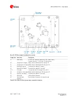
3.3.2
USB interface
The USB host communication for the VERA-P1 module is provided through the micro USB connector
J2 on the power supply board. The connector J2 is connected to a USB 2.0 hub on the power supply
board, which connects the USB port to the following downstream devices:
The USB interface of the VERA-P1 module on the main board
The u-blox NEO-M8U GNSS module on the main board via a USB-to-UART bridge (FT234XD-T)
The SPI interface of the VERA-P1 module or on-board SPI flash on the main board via a USB-to-
SPI bridge (FT2232H port A)
3.3.3
Bootstrapping
The bootstrapping jumper J112 on the main board is used to select the boot mode of the VERA-P1
module. The valid bootstrap options are listed in Table 7. To set a logic level 0, connect the boot pin
with a jumper to GND. Leave the pin open for logic level 1.
Boot mode Boot 2
Boot 1
Boot 0
Description
SPI master 1
1
0
VERA-P1 acts as an SPI master and automatically downloads a
bootloader or firmware from an SPI flash.
SPI slave
1
0
1
Firmware download is under the control of an external SPI master.
VERA-P1 acts as SPI slave.
USB-DFU
1
0
0
USB Device Firmware Upgrade (DFU) boot mode. The VERA-P1 module
presents itself on the USB bus as a DFU device for downloading the
SDR firmware.
Table 7: Boot mode configuration
The EVK-VERA-P174 contains an on-board SPI flash to support the SPI master boot option. See
section 3.3.5 for further configuration of the SPI chip select routing options.
3.3.4
SPI interface
The SPI interface connector J105 on the main board can be used to connect to the SPI interface of
the VERA-P1 module or the on-board SPI flash. The SPI chip select jumpers are used to select either
the VERA-P1 module or the SPI flash.