background image


EVK-N2 - User guide 

UBX-17005115 - R05 

Appendix  

Page 13 of 18 


Appendix  

A


Setting  up  AT  terminal  applications  for 
communication with EVK-N2 

The u-blox m-center cellular module evaluation tool is a powerful platform for evaluating, configuring 
and testing u-blox cellular products. m-center includes an AT commands terminal for communication 
with the device and can be downloaded free-of-charge from our website (http://www.u-blox.com). 
 

1.


Follow the board setup instructions in section 

1.8

 to provide all the required connections and 

switching on the cellular module. 

 
2.


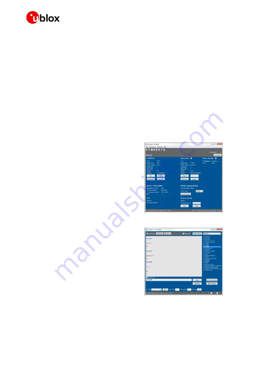
Run the m-center tool: after the m-center start-up, the Home page appears. 

 
3.


On the Home page, set up the AT COM port 
with the setting values described in section 

1.8

. 

Check with the Windows Device Manager to 
find out which COM port is being used by  
EVK-N2. 


Figure 3: “Home” page 

4.


Enable the connection to u-blox cellular 
module by clicking on the Connect button. 

 
5.


Click on the AT Terminal button (upper right 
of the Home page). A new window opens and 
the AT command terminal is now ready for 
communication with EVK-N2. 

 
6.


The AT terminal is ready to use. Click on the 
drop-down menu on the upper right of the AT 
command terminal and select SARA-N2 to 
get the list of supported AT commands.  
For the complete list of AT commands 
supported by the modules and their syntax, 
see the SARA-N2 series AT Commands 
Manual 

[1]

. 

 
7.


In case it is required to collect a trace file, open 
a second m-center window and set the AT 
COM port according to the instructions 
provided in sectio

1.8

. 


The  trace  interface  is  available  over  the 
second numbered COM port opened when a 
USB  cable  is  connected  to  the  mini  USB 
connector (J501)  


Figure 4: AT Terminal window 

 
For more information using the u-blox m-center cellular module evaluation tool, press the F1 key on 
the keyboard to open the m-center help window on the computer. 

Содержание EVK-N2 Series

Страница 1: ...aluation kits User guide Abstract This guide explains how to set up the EVK N2 evaluation kits to begin evaluating u blox SARA N2 series cellular modules supporting LTE Cat NB1 radio access technology...

Страница 2: ...03 UBX 19030865 End of life EVK N280 EVK N280 02B 00 06 57 A07 03 UBX 19030865 End of life u blox or third parties may hold intellectual property rights in the products names logos and designs include...

Страница 3: ...es jumpers and buttons 6 1 4 LEDs 7 1 5 Connectors 8 1 6 EVK N2 pin out 9 1 7 Software installation 10 1 8 Board setup 11 Appendix 13 A Setting up AT terminal applications for communication with EVK N...

Страница 4: ...N280 The evaluation kits EVK N200 EVK N201 EVK N210 EVK N211 and EVK N280 are herein identified as EVK N2 SIM card holder J300 Cellular reset SW303 Cellular power on SW302 GND 9 18 V Power input J400...

Страница 5: ...nna connector and the USB connector for the GNSS module The boards are connected by means of male header board to board connectors provided on the bottom of the adapter boards and their corresponding...

Страница 6: ...VB WL3 Cellular UART routing Slide switch to select cellular module UART routing on USB or on RS232 connectors SW403 EVB WL3 Cellular UART AUX detach Slide switch to attach detach cellular module UART...

Страница 7: ...on the Cellular RS232 connector DL405 EVB WL3 Cellular USB UART AUX Green light is activated when UART AUX is routed to Cellular USB connector Red light blinks at UART AUX data on the Cellular USB co...

Страница 8: ...ellular headset Audio headset jack connector not supported by SARA N2 series J303 EVB WL3 GNSS antenna SMA connector for the GNSS module antenna GNSS Antenna J103 ADP GNSS GNSS USB Mini USB connector...

Страница 9: ...1 J104 Pin 20 33 48 RSVD Not present 17 RSVD Not present 49 RSVD Not present 18 RESET_N Not present 50 GND J104 Pins 7 10 19 RSVD Not present 51 VCC J101 Pins 7 10 20 GND J104 Pins 7 10 52 VCC J101 Pi...

Страница 10: ...t connected 30 29 Not connected Not connected 30 29 Not connected GPIO2 32 31 Reserved_23 Not connected 32 31 Not connected Not connected 34 33 GPIO1 Not connected 34 33 Not connected 1V8 36 35 Not co...

Страница 11: ...the cellular module s UART interface the following connections are allowed and can be alternatively enabled in a mutually exclusive way see Table 6 for slide switches positions and LED status a Conne...

Страница 12: ...face is available over the first COM port for AT commands and data o SARA N2 secondary auxiliary UART interface is available over the second COM port for diagnostic Make sure to appropriately set the...

Страница 13: ...ome page 4 Enable the connection to u blox cellular module by clicking on the Connect button 5 Click on the AT Terminal button upper right of the Home page A new window opens and the AT command termin...

Страница 14: ...gement SIM management module interfaces configurations and other settings see the u blox NB IoT system User Guide 3 C Declaration of conformities The equipment is intended for indoor usage It is the u...

Страница 15: ...ght Agilent 34465A 34410A or 34411A can be used for current consumption measurements in this case the supply circuit on the EVB will supply the SARA N2 module mounted on the adapter board with the dig...

Страница 16: ...Board GND Ground GNSS Global Navigation Satellite System GPIO General Purpose Input Output I2C Inter Integrated Circuit LDO Low Drop Out LED Light Emitting Diode LTE Long Term Evolution NB IoT Narrow...

Страница 17: ...blox documentation and to receive product change notifications register on our homepage www u blox com Revision history Revision Date Name Comments R01 22 Feb 2017 sfal Initial release R02 06 Jun 2017...

Страница 18: ...fice China Beijing Phone 86 10 68 133 545 E mail info_cn u blox com Support support_cn u blox com Regional Office China Chongqing Phone 86 23 6815 1588 E mail info_cn u blox com Support support_cn u b...

Отзывы: