background image

EVK-L20, EVK-L21 - User Guide 

UBX-14000422 - R03 

Early Production Information


Starting up 


Page 8 of 17


1.7


Software installation 

The USB drivers are available with the EVK-L2x. Executable files can be downloaded from www.u-blox.com/evk-
downloads 
and saved to any location on the computer hard drive. The installation can be started by running the 
executable file on a computer with the Windows operating system. 
 

1.8


Board setup 

1.


Insert a SIM card into the 

SIM card holder

 (J300). 

2.


Connect  a  cellular  antenna  provided  with  the  evaluation  kit  box  to  the 

Primary  cellular  antenna

  SMA 

connector (ANT1, J104 on ADP, RF input/output for transmission and reception of LTE/3G/2G RF signals). 

3.


Connect a cellular antenna provided with the evaluation kit box to the 

Secondary cellular antenna

 SMA 

connector  (ANT2,  J103  on  ADP,  RF  input  for  the  reception  of  the  LTE  RF  signals  as  per  the  Down-Link 
MIMO  2  x  2  and  for  the  reception  of  the  3G  RF  signals  as  per  the  Down-Link  Rx  diversity).  Place  the 
secondary cellular antenna far enough from the primary cellular antenna (should be more than 20 cm). 

4.


If the GNSS functionality is required, connect the GNSS antenna provided with the evaluation kit box to the 

GNSS antenna 

SMA connector on the EVB. Place the GNSS antenna in a location with good sky view. 


The interface to the GNSS module is not supported by TOBY-L2x0-00S modules product version. 

5.


Connect the AC / DC +12 V power adapter provided with the evaluation kit box to 

9 – 18 V Power Input


connector (J400). LED DL401 lights blue. 

6.


Be  sure  to  provide  a  jumper  socket  on  the 

Cellular  VCC  supply  jumper

  (J404).  This  provides  the 

connection from the 3.8 V output of the supply circuit on the EVB to the VCC input of the module. 

7.


To  enable  the  board  power  supply,  turn  the 

Main  power  switch

  (SW400)  to  ON  position.  LED  DL400 

lights green. The cellular module switches on. 

8.


For communication via USB, connect the USB cable to the 

Cellular native USB

 connector (J100 on ADP). 

LED  DL100  on  ADP  lights  blue.  After  the  end  of  the  module  boot,  the  following  devices  are  by  default 
enabled with Windows (details as the ports numbering can be seen via the Windows Device Manager)

1

o


Modems 

 u-blox Composite USB Modem Interface 

AT commands interface is available over this modem COM port 

o


Network adapters 

 Remote NDIS based Internet Sharing Device 

Ethernet-over-USB connection is available over this network adapter 

9.


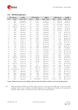
Run an AT terminal application (e.g. the u-blox m-center tool) selecting the u-blox Composite USB Modem 
Interface COM port, with these settings: 

o


Data rate: 115200 b/s 

o


Data bits: 8 

o


Parity: N 

o


Stop bits: 1 

o


Flow control: HW 

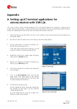
See Appendix A for how to configure the u-blox m-center AT terminal for Windows. 


1

 A message of “driver installation fail” may appear on Windows if the USB cable has been connected before the end of the module boot, 

but this can be ignored as the normal operating functionality of the module will be anyway available after the end of the module boot. 

Содержание EVK-L20

Страница 1: ...EGPRS Cellular evaluation kit User Guide Abstract This guide explains how to set up the EVK L20 and EVK L21 Evaluation Kits to begin evaluating the u blox TOBY L200 and TOBY L210 LTE DC HSPA EGPRS ce...

Страница 2: ...01 15 N A u blox reserves all rights to this document and the information contained herein Products names logos and designs described herein may in whole or in part be subject to intellectual property...

Страница 3: ...ion 8 1 8 Board setup 8 1 9 Enabling error result codes 9 1 10 PIN code insertion when required 9 1 11 Registration on a cellular network 9 1 12 Switching off the EVK L2x 9 Appendix 10 A Setting up AT...

Страница 4: ...K L2x This section describes the main connections and settings required to get started See the TOBY L2 series Data Sheet 2 and TOBY L2 MPCI L2 series System Integration Manual 3 for the features suppo...

Страница 5: ...S adapter board called ADP GNSS contains the u blox GNSS module the GNSS antenna connector and the USB connector for the GNSS module The boards are connected by means of male header board to board con...

Страница 6: ...ular native USB Mini USB connector for cellular module native USB interface J100 ADP L2xx Primary cellular antenna SMA connector for the cellular module primary antenna ANT1 Tx Rx J104 ADP L2xx Second...

Страница 7: ...47 RSVD Not present 78 GND J301 Pins 7 10 17 RXD J301 Pin 16 48 RSVD Not present 79 GND J301 Pins 7 10 18 RSVD Not present 49 RSVD Not present 80 GND J301 Pins 7 10 19 RSVD Not present 50 I2S_WA J300...

Страница 8: ...5 Connect the AC DC 12 V power adapter provided with the evaluation kit box to 9 18 V Power Input connector J400 LED DL401 lights blue 6 Be sure to provide a jumper socket on the Cellular VCC supply j...

Страница 9: ...T CLCK SC 1 8180 OK Lock the PIN at power on the last parameter is the PIN of the SIM card 8180 is written here as an example 1 11 Registration on a cellular network Command sent by DTE user DCE respo...

Страница 10: ...page appears 3 On the Home page set up the AT COM port for the setting values see section 1 8 Check with the Windows Device Manager to find out which COM port is being used by EVK L2x Figure 3 Home pa...

Страница 11: ...0 87 85 23 6 83 224 70 94 83 224 66 138 0 0 OK DNS primary server address is 83 224 70 94 2 LTE case Command sent by DTE user DCE response module Description AT UBMCONF UBMCONF 1 OK Check the networki...

Страница 12: ...f the module registers to an LTE network AT COPS 0 OK Start automatic network registration AT CPIN CPIN READY OK Check the PIN status and act accordingly AT COPS COPS 0 0 I TIM 7 OK Check the COPS AcT...

Страница 13: ...EVK L20 EVK L21 User Guide UBX 14000422 R03 Early Production Information Appendix Page 13 of 17 5 Click on Properties 6 Search for Internet Protocol Version 4 TCP IPv4 and click on Properties...

Страница 14: ...ge 14 of 17 7 Check the Obtain an IP address automatically and Obtain DNS server address automatically option This the DHCP 8 If it is not possible to surf the web then set manually the DNS server add...

Страница 15: ...1 IP my_apn 0 0 0 0 0 0 OK ATD 99 1 CONNECT Initiate the GPRS connection NO CARRIER Disconnect with sequence C 2 SMS management Command sent by DTE user DCE response module Description AT CMGF 1 OK S...

Страница 16: ...u blox AT Commands Manual Docu No UBX 13002752 2 u blox TOBY L2 series Data Sheet Docu No UBX 13004573 3 u blox TOBY L2 MPCI L2 series System Integration Manual Docu No UBX 13004618 4 u blox m center...

Страница 17: ...e 65 6734 3811 E mail info_ap u blox com Support support_ap u blox com Regional Office Australia Phone 61 2 8448 2016 E mail info_anz u blox com Support support_ap u blox com Regional Office China Bei...

Отзывы: