

Ubisense
– Ultra-wideband Location System – UBISENSOR30V1 Revision D
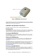
Figure 3
– UBISENSOR30V1 optional dust cover
The optional rear dust cover may be used for installations where the sensor needs additional
protection from the environment. The cover may be fitted with suitable cable glands where the
cables exit from the cover on the bottom surface.
Installation and Operation Instructions
For complete operating instructions, please visit
Mounting options
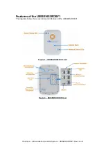
The UBISENSOR30V1 has three mounting holes in the back of the case, to which external
clamps and brackets can be attached. The two outer holes are M4 size, the middle hole is M6
size (and can be used in conjunction with a standard photographic camera mount).
Powering the UBISENSOR30V1
The UBISENSOR30V1 must be powered using Power over Ethernet (PoE). This is normally
done by connecting the unit to a network using a PoE switch. However, it is also possible to
use mid-span injectors if desired.
Setting up the UBISENSOR30V1
The UBISENSOR30V1 must be entered into a configured Ubisense DIMENSION4 dataset.
See
for instructions on how to set up a dataset for your
environment.
Each UBISENSOR30V1 has a unique MAC address, which can be found on the label on the
rear of the unit. By entering the UBISENSOR30V1 in the dataset, and configuring it to
account for the desired system setup, the correct tracking performance can be achieved. See
for full instructions on how to configure UBISENSOR30V1
sensors within the dataset.
Switching on the UBISENSOR30V1
To turn on the UBISENSOR30V1, simply turn on the power to the device. The status LED on
the front of the unit should illuminate, and the device will begin to attempt to contact the
Ubisense location system dataset (which should already have been installed on your network
– see
Optional dust cover
(attaches with four screws)