background image

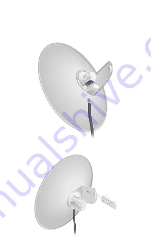
5.  Connect the Ethernet cable:

a.  Connect an Ethe

rnet cable to the Ethernet Port of the 

Antenna Feed

b.  Re-attach the Cable Door to

 the Rear Housing.

20

10

0

10

6.  Slide the Pole Clamp onto the Dish Bracket.

20

10

10

0

Содержание PowerBeam M

Страница 1: ...High Performance Integrated InnerFeed airMAX Bridge Model PBE M5 400...

Страница 2: ...p U Bolt Flange Nuts M8 Qty 2 High Performance Integrated InnerFeed airMAX Bridge Model PBE M5 400 Gigabit PoE 24V 0 5A with Mounting Bracket Power Cord Quick Start Guide The PBE M5 400 Antenna Feed h...

Страница 3: ...re than 10 seconds while the PowerBeam is already powered on Alternatively the PowerBeam may be reset remotely via a Reset button located on the bottom of the Gigabit PoE adapter Release Button After...

Страница 4: ...above 65 dBm LED will light green when the wireless signal strength is above 73 dBm LED will light amber when the wireless signal strength is above 80 dBm LED will light red when the wireless signal...

Страница 5: ...coverage using the 3 dBi Antenna Feed only Installation Requirements 13 mm wrench Shielded Category 5 or above cabling should be used for all wired Ethernet connections and should be grounded through...

Страница 6: ...Dish Reflector Rotate the Dish Bracket counter clockwise until the tabs lock into place 20 10 10 0 2 Line up the Alignment Pins of the Rear Housing with the alignment holes of the Dish Bracket Insert...

Страница 7: ...g 20 10 0 10 4 Attach the Antenna Feed a Insert the Antenna Feed into the Rear Housing and push until it locks into place with a click b Lightly pull the Antenna Feed to ensure that it is locked into...

Страница 8: ...ect the Ethernet cable a Connect an Ethernet cable to the Ethernet Port of the Antenna Feed b Re attach the Cable Door to the Rear Housing 20 10 0 10 6 Slide the Pole Clamp onto the Dish Bracket 20 10...

Страница 9: ...Nut 20 10 10 0 25 N m Note The mounting assembly can accommodate a 32 56 mm pole 8 Optional If you have the PowerBeam Radome optional accessory then align the arrows on the bottoms of the Radome and D...

Страница 10: ...r s power port Connect the other end of the Power Cord to a power outlet Mounting the PoE Adapter Optional 1 Remove the PoE Mounting Bracket from the adapter place the bracket at the desired location...

Страница 11: ...address on the 192 168 1 x subnet 3 Launch your web browser and type https 192 168 1 20 in the address field Press enter PC or return Mac 4 The login screen will appear Enter ubnt in the Username and...

Страница 12: ...drop down list select the appropriate option c Click Change to save d Click OK to confirm Customize additional settings as needed to complete the configuration For additional details on the airOS Conf...

Страница 13: ...er s responsibility to make sure the device is operated within local country regulatory requirements Since Ubiquiti Networks equipment can be paired with a variety of antennas and cables the Antenna a...

Страница 14: ...y Included Power Method Passive PoE Pairs 4 5 7 8 Return Wind Survivability 200 km h 125 mph Wind Loading 342 5 N 200 km h 77 lbf 125 mph Certifications CE FCC IC Mounting Pole Mounting Kit Included O...

Страница 15: ...rovided only by a qualified service technician 3 This equipment is provided with a detachable power cord which has an integral safety ground wire intended for connection to a grounded safety outlet a...

Страница 16: ...V has been subjected to misuse abuse negligence abnormal physical electromagnetic or electrical stress including lightning strikes or accident V has been damaged or impaired as a result of using third...

Страница 17: ...FACILITIES UBIQUITI NETWORKS ITS AFFILIATES AND ITS AND THEIR THIRD PARTY PROVIDERS ARE NOT RESPONSIBLE FOR ANY INTERRUPTIONS DELAYS CANCELLATIONS DELIVERY FAILURES DATA LOSS CONTENT CORRUPTION PACKET...

Страница 18: ...must accept any interference received including interference that may cause undesired operation This equipment has been tested and found to comply with the limits for a Class B digital device pursuan...

Страница 19: ...luding interference that may cause undesired operation of the device This radio transmitter IC 6545A PBE5M has been approved by Industry Canada to operate with the antenna types listed below with the...

Страница 20: ...mp dance pour chacun Informations d antenne Antenne parabolique Gain 25 dBi RF Exposure Warning The antennas used for this transmitter must be installed to provide a separation distance of at least 20...

Страница 21: ...ice or the shop where you purchased the product Deutsch Die Europ ische Richtlinie 2002 96 EC verlangt dass technische Ausr stung die direkt am Ger t und oder an der Verpackung mit diesem Symbol verse...

Страница 22: ...insi que tout autre mat riel lectrique ou lectronique par les moyens de collecte indiqu s par le gouvernement et les pouvoirs publics des collectivit s territoriales L limination et le recyclage en bo...

Страница 23: ...ch Par la pr sente UBIQUITI NETWORKS d clare que l appareil UBIQUITI NETWORKS est conforme aux exigences essentielles et aux autres dispositions pertinentes de la directive 1999 5 CE Deutsch German Hi...

Страница 24: ...lesquiera otras disposiciones aplicables o exigibles de la Directiva 1999 5 CE Polski Polish Niniejszym Ubiquiti Networks o wiadcza e urz dzenie UBIQUITI NETWORKS jest zgodny z zasadniczymi wymaganiam...

Отзывы: