106636-04 - 8/22
12
X-2
Installation, Operating & Service Manual
6
Venting
(continued)
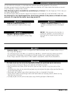
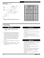
Figure 6-4: Termination Location for Gas Vent
Roof Slope Heights (H)
Roof Slope
ft.
Flat to 6/12
1.0
Over 6/12 to 7/12
1.25
Over 7/12 to 8/12
1.5
Over 8/12 to 9/12
2.0
Over 9/12 to 10/12
2.5
Over 10/12 to 11/12
3.25
Over 11/12 to 12/12
4.0
Over 12/12 to 14/12
5.0
Over 14/12 to 16/12
6.0
Over 16/12 to 18/12
7.0
Over 18/12 t 20/12
7.5
Over 20/12 to 21/12
8.0
7
Water Piping
WARNING
Failure to properly pipe boiler may result in
improper operation and damage to boiler or
building.
!
1. Design and install boiler and system piping to
prevent oxygen contamination of boiler water.
Oxygen contamination sources are system leaks
requiring addition of makeup water, fittings,
and oxygen permeable materials in distribution
system. Eliminate oxygen contamination by
repairing system leaks, repairing fittings, and
using non-permeable materials in distribution
system.
2. Install circulator with flanges, gaskets and bolts
provided.
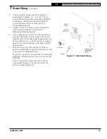
3. Install Safety Relief Valve. See Figure 7-1. Safety
Relief Valve must be installed with spindle in
vertical position.
DANGER
• Pipe relief valve discharge to a safe location.
• Do not install any valves between boiler and
relief valve.
• Do not install any valves between relief valve and
discharge.
• Do not move relief valve from factory location.
• Do not plug relief valve discharge.
• Do not install a relief valve with a setting greater
than 30 psi.
!
WARNING
• Pipe discharge of relief valve to a location where
water will not create a hazard or cause property
damage if the relief valve opens.
• End of discharge pipe must terminate in an
unthreaded pipe.
• Relief valve must terminate no greater than 6
inches above floor.
• Termination of the relief valve discharge piping
must be in an area where it is not likely to
become plugged by debris or subjected to
freezing.
• Union may be installed in safety relief valve
piping.
!


