


SARA-G3 series - System Integration Manual
UBX-13000995 - R06
Objective Specification
System description
Page 47 of 218
1.9
Serial interfaces
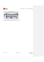
SARA-G3 series modules provide the following serial communication interfaces:
UART interface: 9-wire unbalanced 1.8 V asynchronous serial interface available for AT commands
interface, Packet-Switched / Circuit-Switched Data communication, FW upgrades by means of the
FOAT feature
Auxiliary UART interface: 3-wire unbalanced 1.8 V asynchronous serial interface available only for the
FW upgrade by means of the u-blox EasyFlash tool and for the Trace log capture (debug purpose)
DDC interface: I
2
C compatible 1.8 V interface available only for the communication with u-blox
positioning chips and modules
1.9.1
Asynchronous serial interface (UART)
1.9.1.1
UART features
The UART interface is a 9-wire 1.8 V unbalanced asynchronous serial interface, and it is the only serial
interface of the SARA-G3 modules available for an AT command interface and for Packet-Switched /
Circuit-Switched Data communication.
The module firmware can be upgraded over the UART interface by means of the Firmware upgrade over
AT (FOAT) feature only: for more details refer to section 1.13 and
Firmware update application note
[22].
UART interface provides RS-232 functionality conforming to the ITU-T V.24 Recommendation (more
details available in
ITU Recommendation [9]), with CMOS compatible signal levels: 0 V for low data bit
or ON state, and 1.8 V for high data bit or OFF state. For detailed electrical characteristics refer to
SARA-G3 series Data Sheet [1].
SARA-G3 modules are designed to operate as a GSM/GPRS wireless modem, which represents the data
circuit-terminating equipment (DCE) as described by the
ITU-T V.24 Recommendation [9]. A customer
application processor connected to the module through the UART interface represents the data terminal
equipment (DTE).
The signal names of the UART interface of the SARA-G3 modules conform to the
ITU-T V.24
Recommendation [9]: e.g.
TXD
line represents the data transmitted by the DTE (application
processor data output) and received by the DCE (module input).
The UART interface is controlled and operated with:
AT commands according to
3GPP TS 27.007 [10]
AT commands according to
3GPP TS 27.005 [11]
AT commands according to
3GPP TS 27.010 [12]
u-blox AT commands
For the complete list of supported AT commands and their syntax refer to the
u-blox AT
Commands Manual [2].