background image

EVK-M8L User Guide 


UBX-20028627 - R01 

Specifications  

Page 6 of 33 

C1-Public 


2


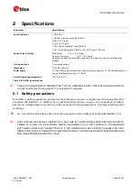
Specifications 

Parameter 

Specification 

Serial interfaces 

1 USB V2.0  
1 RS232, max. baud rate 921.6 kBd 
DB9 +/- 12 V level  
14 pin – 3.3 V logic 
1 DDC (I2C compatible) max. 400 kHz 
1 SPI – clock signal max 5.5 MHz – SPI DATA max. 1 Mbit/s 

Speed Pulse interface 

Wheel tick: 

3.3 V – 24 V logic  

Forward / Reverse: 

3.3 V – 24 V logic 

Separate isolated vehicle GND connection for wheel tick and Forward/Reverse 
signals. 

Timing interface 

Time-pulse output 

Dimensions 

105 x 64 x 26 mm 

Power supply 

5 V via USB or external powered via extra power supply pin 14 (V5_IN) and common 
supply/interface ground pin 13 (GND) 

Normal Operating temperature  

-40 °C to +65 °C 

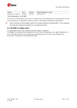
Table 2: EVK-M8L specifications 


THE EVK CASE-WORK IS CONNECTED TO THE COMMON SUPPLY/INTERFACE GROUND PIN. 
Contact u-blox technical support for assistance if required.  

2.1


Safety precautions  

EVK-M8L must be supplied by an external limited power source in compliance with clause 2.5 of the 
standard  IEC  60950-1.  In  addition  to  an  external  limited  power  source,  only  separated  or  Safety 
Extra-Low Voltage (SELV) circuits are to be connected to the evaluation kit, including interfaces and 
antennas.  


For more information about SELV circuits see section 2.2 in Safety standard IEC 60950-1 [7]. 


CAUTION! IN THE UNLIKELY EVENT OF A FAILURE IN THE INTERNAL PROTECTION CIRCUITRY 
THERE  IS  A  RISK  OF  EXPLOSION  WHEN  CHARGING  FULLY  OR  PARTIALLY  DISCHARGED 
BATTERIES. REPLACE THE BATTERY IF IT NO LONGER HAS SUFFICIENT CHARGE FOR UNIT 
OPERATION. CHECK THE BATTERY BEFORE USING IF THE DEVICE HAS NOT BEEN OPERATED 
FOR AN EXTENDED PERIOD OF TIME. 

Содержание EVK-M8L

Страница 1: ...ser guide Abstract This document describes the structure and use of the EVK M8L evaluation kit and provides information for evaluating and testing u blox M8 ADR positioning technology www u blox com UBX 20028627 R01 C1 Public ...

Страница 2: ...n Firmware version PCN reference Product status EVK M8L EVK M8L 0 12 D Flash FW 3 01 ADR 4 31 M8L N A Production information European Union regulatory compliance EVK M8L complies with all relevant requirements for RED 2014 53 EU The EVK M8L Declaration of Conformity DoC is available at www u blox com under Support Product Resources Conformity Declaration u blox or third parties may hold intellectu...

Страница 3: ...8 3 3 5 Safe boot button 8 3 3 6 Slide switch 9 3 3 7 Front connector 9 3 3 8 LED 10 3 3 9 Backup battery 10 3 3 10 GNSS configuration 11 4 Setting up 12 4 1 Test vehicle preparation 12 4 1 1 Wiring harness of the Head Unit 12 4 1 2 OBD II to VSS converter 13 4 1 3 Wheel speed sensor 13 4 2 EVK M8L installation 13 4 2 1 Mounting the GNSS antenna 13 4 2 2 Mounting the EVK M8L 13 4 2 3 Connecting th...

Страница 4: ... User guide UBX 20028627 R01 Page 4 of 33 C1 Public Contents 9 Schematic 27 10 Battery replacement 28 11 Troubleshooting 29 12 Common evaluation pitfalls 31 Related documents 32 Revision history 32 Contact 33 ...

Страница 5: ...t of products supported by the EVK M8L evaluation kit 1 2 Kit includes Evaluation unit USB cable Active GPS Galileo GLONASS BeiDou antenna with 3 m cable Quick Start card 1 3 Evaluation software The u center software installation package for the EVK can be downloaded from www u blox com en evaluation software and tools Once the zip file is downloaded extract the file contents in the Tools folder a...

Страница 6: ...VK M8L specifications THE EVK CASE WORK IS CONNECTED TO THE COMMON SUPPLY INTERFACE GROUND PIN Contact u blox technical support for assistance if required 2 1 Safety precautions EVK M8L must be supplied by an external limited power source in compliance with clause 2 5 of the standard IEC 60950 1 In addition to an external limited power source only separated or Safety Extra Low Voltage SELV circuit...

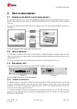
Страница 7: ...sive GNSS antennas with SMA connectors to the evaluation unit The recommended maximum antenna supply current for active antennas is 30 mA 3 3 Evaluation unit Figure 2 shows the front and the rear panel of the EVK M8L evaluation unit Front panel Rear panel Figure 2 EVK M8L evaluation unit front and rear panels 3 3 1 Antenna connector An SMA female jack is available on the front side see Figure 2 of...

Страница 8: ...le connector is assigned as listed in Table 3 Pin no Assignment 1 not connected 2 TXD GNSS Transmit Data serial data to DTE 3 RXD GNSS Receive Data serial data from DTE 4 not connected 5 GND 6 not connected 7 9 not connected Table 3 SUB D9 connector pin description for EVK M8L 3 3 4 RST button The RST button on the front panel resets the unit To avoid an inadvertent reset the button is recessed 3 ...

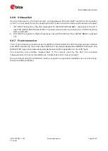
Страница 9: ...ed 2 SPI With this selection the EVK operates only with the SPI interface RS232 DB9 is switched off 3 3 7 Front connector This 14 pin connector provides access to additional functionality to the EVK using various interface pins Most importantly it provides the interface to the vehicle speed pulse WHEELTICK input The WHEELTICK signal should be adequately de bounced before application to the EVK inp...

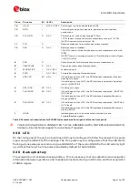
Страница 10: ...utput 3 TxD MISO I O 3 3 V If the slide switch is on I2C the DDC interface is selected UART TxD 3 3 V level If the slide switch is on SPI the SPI interface is selected Master in Slave out MISO 2 RxD MOSI I O 3 3 V If the slide switch is on I2C the DDC interface is selected UART RxD 3 3 V level If the slide switch is on SPI the SPI interface is selected Master out Slave in MOSI 1 GNDA I Isolated gr...

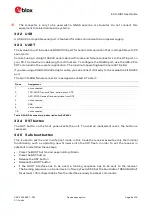
Страница 11: ...scribed above for replacement refer to section 10 for battery replacements guidelines CAUTION RISK OF EXPLOSION IF BATTERY IS REPLACED BY AN INCORRECT TYPE DISPOSE OF USED BATTERIES ACCORDING TO THE INSTRUCTIONS 3 3 10 GNSS configuration The EVK M8L supports GPS QZSS GLONASS Galileo and BeiDou The GNSS to be used can be configured in u center View Messages View UBX CFG GNSS For more information re...

Страница 12: ...ive with some compromise in performance Shall be a series of absolute wheel tick pulses with one pulse corresponding to less than 0 4 meters of distance traveled For best results one pulse should correspond to about one centimeter of distance traveled Shall be available regardless of the direction of driving Shall be adequately de bounced before application to the EVK input The FWD signal Shall in...

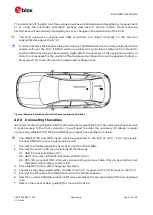
Страница 13: ... However even one wheel provides sufficiently good measurement for most evaluation purposes Several manufacturers offer these sensors for example Peiseler GmbH and PEGASEM Messtechnik GmbH Figure 3 WSS2 wheel speed sensor from PEGASEM Messtechnik GmbH WSS2 provides wheel tick and direction signals 4 2 EVK M8L installation The EVK M8L ships with an active GPS GLONASS BeiDou magnetic mount antenna w...

Страница 14: ...ntenna and the EVK M8L 4 2 3 Connecting the cables We recommend using the ACE AM 0 mating connector available from the u blox web shop because it locks securely to the front connector You will need to solder the necessary I O cables to signal sources e g WHEELTICK FWD and GNDA and outputs as specified in Table 6 The WHEELTICK and FWD inputs must be presented to the EVK at 3 3 V 24 V logic levels C...

Страница 15: ...e receiver may be configured to use both the rising and falling edges of the wheel tick signal on the condition that the wheel tick pulses have approximately 1 1 mark space ratio regardless of speed The wheel tick direction pin polarity is now automatically initialized The car needs to drive with a minimum speed of 30 km h for proper initialization You can also manually establish the polarity of y...

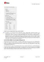
Страница 16: ...ve the configuration permanently and make sure the EVK will always stay in this particular configuration 4 3 2 2 Sensor IMU mount angles configuration Dead reckoning performance relies on accurate configuration of the sensor mount configuration angles The angles may be measured and configured manually or established using the Automatic IMU mount Alignment feature described below In either case the...

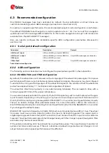
Страница 17: ...nfiguration values yaw pitch roll shall be issued again For example in the basic use case when the EVK M8L is mounted flat label side up and X axis on the label is pointing forward the user should configure it in UBX CFG ESFALG as yaw pitch roll 0 0 0 4 3 2 3 Saving the configuration permanently If for example automatically determined IMU mount angles should be used after the next cold start they ...

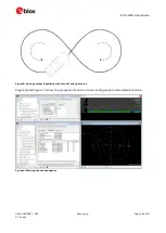
Страница 18: ...o ensure quick calibration the driving location needs to have very good GNSS visibility The terrain needs to be flat and speed must be high enough The calibration time can be improved if the following procedure is carried out Drive the car to an open area An example of a suitable place is a very large empty parking area Use u center to monitor the process enable the UBX ESF STATUS message Phase I ...

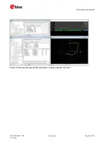
Страница 19: ...R01 Setting up Page 19 of 33 C1 Public Figure 8 Driving number 8 patterns with fast left and right turns Figure 9 and Figure 10 show the progress of sensor mount configuration and calibration drive Figure 9 Starting the drive sequence ...

Страница 20: ...EVK M8L User Guide UBX 20028627 R01 Setting up Page 20 of 33 C1 Public Figure 10 All sensors have reached Calibrated status The setup is ready for test drives ...

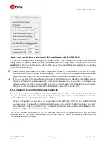
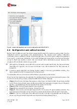
Страница 21: ...a of your test drives You can enable additional debug messages by clicking the Debug button and then clicking the Record button see Figure 11 When prompted to poll for configuration click Yes see Figure 12 Figure 11 The Debug and Record buttons are used for extra messages and debugging post analysis Figure 12 Allow polling and storing of the receiver configuration into log file ...

Страница 22: ...ad all the Aiding Data via the AssistNow Online service 3 Read the voltage and average if necessary on the voltmeter and convert to current 1 mV equals 1 mA 4 Perform the test with good signals and clear sky view to ensure that the receiver can acquire the satellite signals The overall current measurement also includes the internal SQI flash For ROM based products the current will be lower For mor...

Страница 23: ...EVK M8L User Guide UBX 20028627 R01 Block diagram Page 23 of 33 C1 Public 7 Block diagram Figure 14 EVK M8L block diagram ...

Страница 24: ...L User Guide UBX 20028627 R01 Board layout Page 24 of 33 C1 Public 8 Board layout Figure 15 shows the EVK M8L board layout PCB Version D See Table 7 for the component list of the EVK Figure 15 EVK M8L layout ...

Страница 25: ...GHT JACK 11 4 MM HEIGHT WITHOUT WASHER AND NUT J3 9 POLE SUBD CONNECTOR FEMALE J4 14 PIN 90 2 54 MM PITCH DISCONNECTABLE CRIMP CONNECTOR 40 85 C L1 IND MURATA LQW15A 0402 8N7 3 0 54 A 55 125 C L2 IND MURATA LQW15 A 0402 120N 5 0 64 A 55 125 C Q1 MBT3906DW1T1G DUAL GENERAL PURPOSE TRANSISTOR 0 2A 0 15W 40 125 C R1 RES THICK FILM CHIP 1206 10R 5 0 25 W R10 RES THICK FILM CHIP 0402 220R 5 0 1 W R11 R...

Страница 26: ...MIC 1 575 GHZ 1 5 V 3 6 V JRC EPFFP6 A2 3 6 V 40 85 C U6 RS 232 TRANSCEIVER 1MBIT 3 5 5 VOLT TRSF3223 VQFN20 5 5 V 40 85 C U7 TINY LOGIC ULP A 2 INPUT AND GATE 1 45 X1 0 6 LEAD MICROPAK 40 85 C U8 U10 OPTOCOUPLER LVTTL LVCMOS COMPATIBLE AVAGO HCPL 070L 000E SO8 U11 U12 TINY LOGIC UHS INVERTER WITH SCHMITT TRIGGER FAIRCHILD NC7SZ14 SOT23 5 Table 7 EVK M8L component list ...

Страница 27: ...EVK M8L User Guide UBX 20028627 R01 Schematic Page 27 of 33 C1 Public 9 Schematic Figure 16 Schematic EVK M8L DNI TRUE in the schematic means Component not installed ...

Страница 28: ...e UBX 20028627 R01 Battery replacement Page 28 of 33 C1 Public 10 Battery replacement To replace the battery number 5 in Figure 17 open the unit unscrew four screws on the front panel Figure 17 EVK M8L battery location ...

Страница 29: ...show up in the COM port drop down list If a COM Port is gray another application running on this computer is using it The position is inaccurate by a few dozen meters u blox M8 GNSS technology starts up with the WGS84 standard GNSS datum If your application expects a different datum you will most likely find the positions to be off by a few dozen meters Do not forget to check the calibration of u ...

Страница 30: ...0 degrees Do not rely on UBX ESF ALG in this case To solve the issue measure the angles and use manual configuration OR install the device in an orientation where automatic configuration can be used Cannot reach fine accelerometer calibration If the wheel tick resolution is about 25 cm or worse the accelerometer calibration may not reach fine as shown in UBX ESF STATUS However even coarse calibrat...

Страница 31: ...e an impact on signal travel time The position of the GNSS receiver is typically not the same between two tests Comparative tests should therefore be conducted in parallel by using one antenna and a signal splitter statistical tests shall be run for 24 hours Monitor the Carrier To Noise Ratio The average C No ratio of the high elevation satellites should be between 40 dBHz and about 50 dBHz A low ...

Страница 32: ...ncluding Protocol Specification UBX 13003221 6 u center User guide UBX 13005250 7 Information technology equipment Safety Standard IEC 60950 1 webstore iec ch publication 4024 For regular updates to u blox documentation and to receive product change notifications register on our homepage www u blox com Revision history Revision Date Name Status Comments R01 06 Aug 20 njaf Updated firmware informat...

Страница 33: ...nal Office China Beijing Phone 86 10 68 133 545 E mail info_cn u blox com Support support_cn u blox com Regional Office China Chongqing Phone 86 23 6815 1588 E mail info_cn u blox com Support support_cn u blox com Regional Office China Shanghai Phone 86 21 6090 4832 E mail info_cn u blox com Support support_cn u blox com Regional Office China Shenzhen Phone 86 755 8627 1083 E mail info_cn u blox c...

Отзывы: