- 113 -
7. Appendix
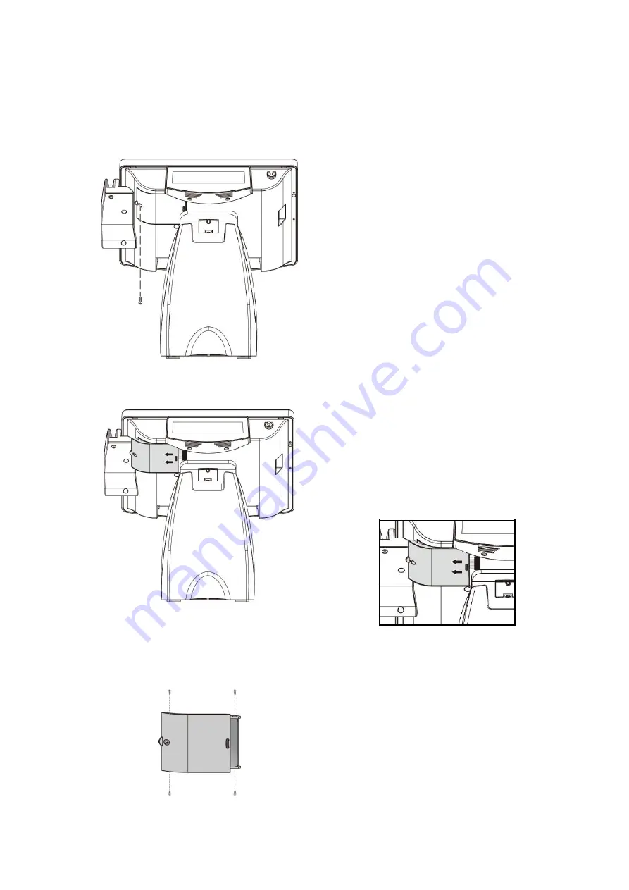
7.1. Replace the Hard Disk
a.
Remove the securing screw of the
HDD cover from the POS unit.
b.
Remove the HDD Cover from the
POS unit.
Pull the HDD Module to the left to
detach it from the POS unit.
Disconnect the HDD Cable to remove
the HDD Module.
Remove the HDD Module
(in the HDD Cover)
HDD Cover
(HDD Inside)
Securing Screws
Securing Screws
c.
Loosen the securing screws to
remove the hard disk from the
bracket.
Then replace a new hard disk
d.
Secure to the HDD module back to
the HDD cover
e.
Re-install the HDD Cover (with new
HDD) back to the POS unit.
Securing
Screw
Содержание POP-650-i
Страница 4: ......
Страница 8: ......
Страница 13: ...5 Dimensions Front View Left View Rear View Right View...
Страница 29: ...21 i Click Next to continue j The driver of Virtual Serial Port is successfully installed Click Finish to exit...
Страница 39: ...31 Examine the parameters of selected COM port that fit to the settings of the printer Click OK to exit...
Страница 51: ...43 When selecting theAHCI mode in the SATA Mode Selection it will display the following information...
Страница 58: ...50 Serial Port 3 to Serial Port 6 Configurations Port 3 Port 4...
Страница 60: ...52 3 2 9 Network Stack This section configures settings relevant to the network stack...
Страница 65: ...57 3 3 Chipset This field is used to configure the functions of relevant chipset...
Страница 70: ...62 3 3 2 System Agent SA Configuration...
Страница 73: ...65 Memory Configuration This field displays the memory configuration...
Страница 75: ...67 CSM Parameters Launch Storage OpROM policy Control the execution of UEFI and legacy storage OpROM...
Страница 76: ...68 3 5 Security Administrator Password Set the administrator password User Password Set the user password...
Страница 79: ...71...
Страница 83: ...75 b Setup is now installing the driver c Setup completed Click Exit to close the program...
Страница 90: ...82 c Click Finish to finish the installation...
Страница 94: ...86 f Double click the file Setup EXE to start the installation g Click Next to start the installation...
Страница 107: ...99 e Select Install driver only and click Next to continue f Click Install to begin Installation...
Страница 128: ...120 7 5 3 COM 5 Jumper Setting JP19 JP19 allows you to select the power and signal type of the COM 5 port...
Страница 129: ...121 7 5 4 Cash Drawer Power Select J2 J2 is used to select the power level that supplies with the cash drawer...
Страница 130: ...122 7 5 5 Jumper Location and Settings...
Страница 131: ...123 7 5 6 Jumper Settings...
Страница 132: ...124...
Страница 133: ...125 20161225...


