background image

8

8

9

9

10

10

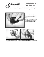
Install the bobbin B to the bobbin winder spindle, 
pass the thread A between the tension disc E, and 
then wind the thread a few turns around the bobbin.
 Lift the lever D to make the latch lever C lock the
 bobbin B. The machine will automatically wind 
when sewing.(Lift the presser foot when wind 
without running the machine.)
Do not overfill the bobbin, as it will make the thread
 loosen down from the bobbin. The optimum capacity
 of thread will be about 80% of the outside diameter 
of the bobbin. The winding amount can be adjusted 
by screw H.
After the bobbin is filled, the bobbin thread could be
cut down with the thread-cutting blade. Wind the 
bobbin thread A two turns around the blade, then pull
it.

11. Winding the bobbin thread (Fig.8)

11. Winding the bobbin thread (Fig.8)

When threading the needle thread, raise  the  needle 
bar to its highest position, open the roller foot,  then 
lead the thread from the spool and pass it in the order
 instructed.
1. Leading the thread down through the two-eye thread 
guide 1 on the top of the machine.
2. To left pass the thread  through right hole  of  thread 
guide, then pass down it through the  thread  tension 
disc 2.
3. Pass down through the thread tension disc 3.
4. To left pass through the thread control assembly 4.
5. Pass up through the upper thread guide 5,then pass 
through the thread hole of the  thread  take-up  lever 
from right to left.
6.Pass down through the middle thread guide 6,lower
 thread guide 7 and needle bar thread  guide  8,  then 
pass through the  hole  of the  needle  9 and draw out 
over 100mm. 

12. Threading (Fig.9) 

12. Threading (Fig.9) 

1. Open the rotating hook guard A.
2. Lift the bobbin case latch lever B.
3. Draw out the threads about 50mm from the notch  of 
the bobbin case.
4. Install the bobbin case into the rotating hook.
5. Close the bobbin case latch lever B.
6. Hold the needle thread by left hand, and turn the 
balance wheel by right hand to put aside the  bobbin 
thread.
7. Close the rotating hook guard A.

13. Installing the bobbin and the bobbin case (Fig.10)

13. Installing the bobbin and the bobbin case (Fig.10)

Содержание GC24660

Страница 1: ...Post bed Single Needle Upper and Lower Roller Feed Sewing Machine R GC24660 GC24680 OPERATION INSTRUCTION PARTS MANUAL Post bed Twin Needle Upper and Lower Roller Feed Sewing Machine...

Страница 2: ...391371 63391627 POST CODE 215223 Http www typicalwpchina com E mail bzwf public1 sz js cn TYPICAL SEWING MACHINE WANPING MACHINERY CO LTD Please don t adjust and repair the machine by non professional...

Страница 3: ...machine 28 29 11 Threadwinder 30 31 12 Accessories 32 33 1 Brief introduction 1 2 Main technical specification 1 3 Preparation 1 4 Installing the machine 1 5 Installing the motor 2 6 Connecting pedal...

Страница 4: ...otating hook Rotating hook vertical rotating hook vertical rotating hook Needle gauge Needle gauge 2 4mm standard 1 2mm 1 6mm 2mm 3 2mm 4mm 2 4mm standard 1 2mm 1 6mm 2mm 3 2mm 4mm Lubrication Lubrica...

Страница 5: ...cally The proper tension of the V belt is a slack of 10 12mm when the belt is depressed on the belt pan by finger 1 The optimum tilt angle of pedal with floor is approx 15 degree 2 Adjust the motor cl...

Страница 6: ...lance wheel to lift the needle bar to its highest position 2 Open the roller presser foot A 3 Loosen the needle set screw B 4 When installing single needle machine the long groove of the needle should...

Страница 7: ...ion disc 2 3 Pass down through the thread tension disc 3 4 To left pass through the thread control assembly 4 5 Pass up through the upper thread guide 5 then pass through the thread hole of the thread...

Страница 8: ...the needle pick through the materials 5 Put down the presser foot lift lever 6 The thread should be drawn out about 100mm for the first sewing 1 Lift the presser foot lift lever 2 Close the roller fo...

Страница 9: ...hread breakage the tension of needle thread and bobbin thread must be adjusted accordingly 1 If the stitch form is the same with B it indicates that the needle thread is too strong and the bobbin thre...

Страница 10: ...e out the hook head 8 f Tighten the set screw 9 and take out the hook cover 10 2 Installing the rotating hook Install the rotating hook in the reverse order of replacing it When inserting the bobbin c...

Страница 11: ...1 8mm from its lowest position the position of the rotating hook and the needle should be set as shown in Fig 18 1 The top of needle eye should be 1 0 3mm lower than the hook point 2 Hook point is ali...

Страница 12: ...about 0 05mm which has been adjusted before del ivery The readjustment is needed only when the needle is changed 1 Take out the hook cover 2 Put down the machine head 3 Take off the bevel gear oil cas...

Страница 13: ...1 Arm and bed 1 Arm and bed...

Страница 14: ...ort Screw short Rear cover Rear cover Screw Screw Rear cover Rear cover Screw Screw Arm Arm Screw Screw Support bracket Support bracket Screw Screw Bed support Bed support Rubber plug Rubber plug Scre...

Страница 15: ...2 Thread tension parts 2 Thread tension parts...

Страница 16: ...late Thread tension disc Thread tension disc Thread releasing pin Thread releasing pin Thread releasing pin short Thread releasing pin short Nut Nut Spring Spring Thread tension disc Thread tension di...

Страница 17: ...3 Upper shaft thread take up parts 3 Upper shaft thread take up parts...

Страница 18: ...ar adapter Screw Screw Seal ring Seal ring Retainer Retainer Needle bar crank Needle bar crank Screw Screw Screw Screw Screw Screw Screw Screw Upper shaft Upper shaft Front bearing complete Front bear...

Страница 19: ...4 Needle bar parts 4 Needle bar parts...

Страница 20: ...rating cam Screw Screw Rubber plug Rubber plug Connecting shaft Connecting shaft Spacer Spacer Needle bearing Needle bearing Pin Pin Pin Pin Crank Crank Screw Screw Screw Screw Collar Collar Screw Scr...

Страница 21: ...5 Feed mechanism 5 Feed mechanism...

Страница 22: ...djusting pad Adjusting pad Washer Washer Screw Screw Eccentric adjusting disc Eccentric adjusting disc Washer Washer Nut Nut Block Block Screw Screw Adjusting bracket for stitch length Adjusting brack...

Страница 23: ...6 Presser bar lifter parts 6 Presser bar lifter parts...

Страница 24: ...pring Presser foot rail Presser foot rail Screw Screw Presser bar lifting rod Presser bar lifting rod Screw Screw Pin Pin Draw bar Draw bar Screw Screw Nut Nut Screw Screw Hook Hook Spring Spring Scre...

Страница 25: ...7 Upper roller feed parts 7 Upper roller feed parts...

Страница 26: ...osition block Screw Screw Bearing Bearing Retainer Retainer Spacer Spacer Clutch bearing holder Clutch bearing holder Clutch Clutch Driven shaft Driven shaft Bevel gear Bevel gear Bevel gear pin Bevel...

Страница 27: ...8 Lower shaft 8 Lower shaft...

Страница 28: ...shing Bushing Screw Screw Lower shaft front Lower shaft front Lower shaft front Lower shaft front Lower shaft rear Lower shaft rear Shaft connector Shaft connector Screw Screw Screw Screw Connecting p...

Страница 29: ...9 Post bed 9 Post bed...

Страница 30: ...Spacer Rubber plug Screw Adjusting cam Screw Screw Washer Cover Spring plate Screw Bushing Rotating hook case Hinge Hinge pin Cover Cover Needle plate Roller Bearing Screw Spacer Thread distributor F...

Страница 31: ...10 Post bed parts only for double needle machine 10 Post bed parts only for double needle machine...

Страница 32: ...g block Set plate Set plate Right hook post bed Right hook post bed Upper bevel gear Upper bevel gear Position ring Position ring Spacer Spacer Bearing Bearing Vertical shaft Vertical shaft Needle bea...

Страница 33: ...11 Thread winder 11 Thread winder...

Страница 34: ...her Thread base Crank Pin Screw Thread spanner Spring plate Screw Screw Screw Spanner shaft Retainer Thread spool Spring Blade Screw Spring Spring Position pin Position pin Thread pass plate Screw Scr...

Страница 35: ...12 Accessory 12 Accessory...

Страница 36: ...er big Screw driver medium Screw driver small Safety guard I Safety guard II Pat long Pat short Screw Screw Washer Screw Small screw Small washer Big screw Oil pot Spool stand assembly Spool stand ass...

Отзывы: