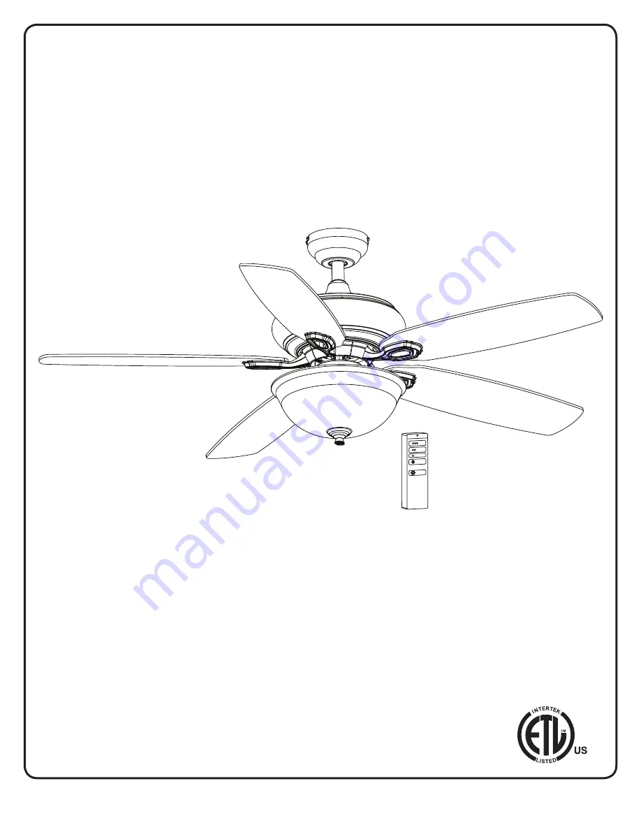
Turn of the century 20261 Скачать руководство пользователя страница 1

9052 • 12/02/13

52”ALBON

CEILING FAN

Owner’s Manual

Models #20261, 20264

Turn of the Century

TM

1

If a problem cannot be remedied or you are experiencing difficulty in installation, 

please contact the Service Department: 1-877-459-3267, 9 a.m.- 5 p.m. Central time.

Содержание 20261

Страница 1: ...EILING FAN Owner s Manual Models 20261 20264 TurnoftheCenturyTM 1 If a problem cannot be remedied or you are experiencing difficulty in installation please contact the Service Department 1 877 459 3267 9 a m 5 p m Central time ...

Страница 2: ...ll Chain Extension x 2 21 Motor Screw x 10 22 Mounting Bracket Screw x 4 23 Blade Screw x 15 24 Closemount Screw x 3 25 Downrod Set Screw x 2 26 Star Washer x4 27 Blade Washer x 15 28 Switch Housing Screw x 3 29 Plug Button 30 Wire Connector x 3 31 Downrod Clip 32 Downrod Pin 33 Blade Isolator x 5 Unpack your fan and check the contents You should have the following items PACKAGE CONTENTS HARDWARE ...

Страница 3: ... method is best suited for ceilings lower than 8 feet It does not utilize the downrod Downrod Mount is best suited for ceilings 8 ft or higher For taller ceilings you may want to use a longer downrod not included Angled Ceiling Mount is best suited for angled or vaulted ceilings A longer downrod is sometimes necessary to ensure proper blade clearance from the ceiling If using the angle mount check...

Страница 4: ...by the person s installing caring for and operating the fan TO AVOID RISK OF ELECTRIC SHOCK BE SURE TO SHUT OFF POWER AT THE MAIN FUSE OR CIRCUIT BREAKER BOX BEFORE INSTALLING OR SERVICING THIS FIXTURE TURNING OFF THE ELECTRICAL POWER BY USING THE LIGHT SWITCH IS NOT SUFFICIENT TO PREVENT ELECTRICAL SHOCK TO REDUCE THE RISK OF INJURY INSTALL THE FAN SO THAT THE BLADES ARE AT LEAST 7 FEET 2 1 METER...

Страница 5: ...for fan support and use the mounting screws and washers provided with the outlet box 4 3 Remove the motor screws from the underside of the motor Discard the motor blocks and washers but keep the motor screws for later If you wish to use the Downrod Mount shown on page 3 proceed to Step 5 4 CLOSEMOUNT INSTALLATION OPTIONAL a Remove the canopy cover from the bottom of the canopy b Align the holes in...

Страница 6: ... downrod clip Then retighten the set screws 8 With wiring extending out of the downrod measure 8 inches of lead wire and cut the excess wire with wire cutters not included Then strip 1 2 of insulation from the end of each wire Then lift the downrod into the mounting bracket Rotate the downrod until the tab in the mounting bracket is seated in the slot in the downrod ball Downrod Clip Downrod Canop...

Страница 7: ...wiring diagram and the following instructions Connect the blue wire with white label from receiver to blue light power wire from fan Connect the black wire with white label from receiver to black fan power wire from fan Connect the red wire with red label from receiver to black hot power supply wire Connect the white wire with red label from receiver to white neutral common supply wire Connect the...

Страница 8: ...nto the sockets in the light kit 16 Remove the finial cap and finial from threaded rod on the light kit Feed fan pull chain coming from the switch housing down through the grommet in the lower part of the light kit 14 Switch Housing Single pin Connector Switch Housing Screw Grommet Finial Cap Finial Light Kit Blade Arm Motor Screw Blade Isolator Motor 13 13 Secure the blade arm and blade isolator ...

Страница 9: ...ap to the bottom of the switch housing with the three switch housing screws d Insert plug button into center of switch housing cap e Attach the pull chains extension Step 18 f Restore the power at the main fuse or circuit breaker Switch Housing Cap Plug Button Switch Housing Screw 20 18 Pull Chain Extension 17 Feed the pull chains through the appropriate holes in the glass shade finial plate and t...

Страница 10: ... from the back of the remote transmitter and insert the 12 volt battery Replace the battery cover D CFL Switch Located inside the battery compartment in remote transmitter The switch is pre set to CFL The switch should be moved from CFL to D for dimming incandescent bulbs included IMPORTANT The dimmer function does NOT work with CFL bulbs 3 To operate the fan using remote control press and release...

Страница 11: ...insulator Replace glass and tighten screws against rubber band 5 Some fan motors are sensitive to signals from Solid State variable speed controls DO NOT USE a Solid State variable speed control 6 Allow break in period of 24 hours Most noises associated with a new fan will disappear after this period 1 Ensure all blades are screwed firmly into blade arms 2 Ensure all blade arms are tightened secur...

Страница 12: ... any implied warranty including but not limited to any implied warranty of merchantability or fitness for a particular purpose become void This warranty and any implied warranty including but not limited to any implied warranty of merchantability or fitness for a particular purpose do not cover glass globes light bulbs or finish on any metal portions of the fan This warranty is in lieu of express ...

Отзывы: