53
1. Base condition number: 1~10
2. Reference condition switch: on/off.
3. Note: make a note for the current reference point.
4. Output IO at the reference point: When the robot position reaches the position of
the reference point, IO outputs a high level, otherwise enters a low level.
5. Detection method: the method for acquiring whether the robot is at the reference
position. Respectively, command position or current position..
6. Return to reference point input IO: When the input IO is a rising edge, the robot
will return to the reference point.
7. Trigger mode for returning to reference point: There are three ways to return to the
reference point: joint motion, linear motion and command file,
8. Return to reference point file: set the instruction file to return to reference point,
9. Reference point left value: the floating (negative) left value when detecting whether
the robot is at the reference point,
10. Reference point: the exact value of the reference point of the robot,
11. Reference point right value: the floating (positive) right value when detecting
whether the robot is at the reference point,
Description:
1) On this page, you can use the SA key joint to run to the reference point, the
prerequisite is that the reference point must be turned on.
2) The reference point can be used in the motion command interface. The prerequisite
is that the datum point must be turned on. When using linear motion to the reference point,
the user and the tool must select 0.
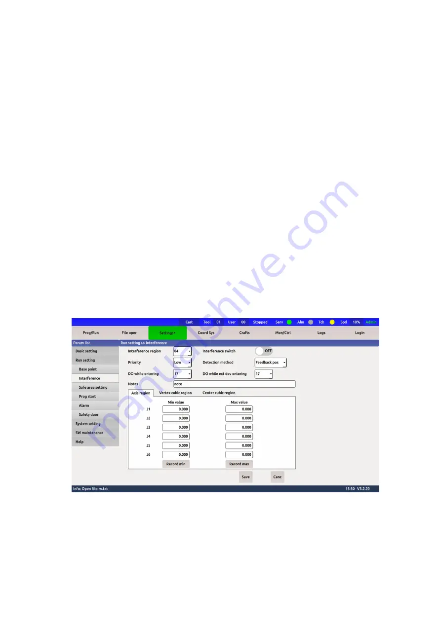
4.3.2 Interference area setting
Figure 4-9 Interference area setting
1. Interference zone number: 1~10.
2. Interference zone switch: on/off .
3. Priority: high/low, when the high priority is set, the interference zone will become
larger (joint angle increases by 0.5 degrees, the spatial position increases by 10mm in each
axis direction), this function can guarantee High priority robots first send a signal to enter
the interference zone.
Содержание TKB80306
Страница 1: ...Shanghai Turing Intelligent Manufacturing Robot Co LTD ...
Страница 6: ...IV IV 8 2 Common faults and treatment 82 ...
Страница 52: ...46 Figure 3 49 Sorting files ...
Страница 56: ...50 Figure 4 4 System V variables Figure 4 5 System S variables ...
Страница 79: ...73 Figure 6 8 Log print settings ...


