22-1002087-0100 Rev B
4. SNTP / Date / Time
n
Select the
SNTP / Date / Time
link and click
Enable
to enable SNTP.
o
Click
Edit
when it becomes selectable.
p
Enter the IP addresses for up to two NTP servers.
q
Select
OK
to continue.
r
Select
Edit
for Node Date and Time. Enter the current Date or select from a
drop down calendar. Enter the current time by selecting the appropriate
hour, minute, and second drop down fields and then select
OK
.
s
Select
Edit
for the time zone.
t
Select the appropriate time zone in Greenwich Mean Time (GMT) from the
drop down field (+12 to -12).
¨
Note:
A TE-2020 node on the ring can be used as an NTP server. When
setting the date and time manually, the corresponding GMT time difference to
the user’s local time zone can simply be acquired from the time zone property
of the user’s computer. All nodes within a network must be set the same time
zone within a network.
¨
Note:
The
Observe DST
is for areas that observe Daylight Saving Time.
This only applies if the network lays within the GMT -4 to GMT -10 zones.
u
Click
OK
to continue.
5. Synchronization
n
Select the
SONET Sync
link in the Quick Install window. The Sync Status,
Mode, switch state, and provisioned priority is shown between the two
available references.
o
Select a valid reference from the available sources. Either OC48-R1-F1,
OC48-R2-F1, or SYNC-INT are available depending on the equipment
installed. Only two sources may be selected at a time.
p
Select
OK
to save changes.
6. Rear Ethernet Management Port
n
Select the
ETH-R IP
link to enter the IP address and netmask for the remote
management system.
SNMP
n
Click the
SNMP
link as shown to enter the Simple Network Management
Protocol IP addresses and information.
Administrate Security
n
Click
Administrate Security
. This feature enables an administrative user
(root) to provision additional users for access to the system and to tailor a
security message for all users that log onto the system.
Configure Alarms
n
Click the
Configure Alarms
link. This option allows the user to quickly set
up the first five environmental alarms on the system.
¨
Note:
A selection is available at the bottom left of the window that enables
the user to pre-provision the alarms for a standard wall mount application. If
using Turin’s optional wall mount cabinet solution, click
Populate with
Defaults for Wall Mount Cabinet
.
Stop! You have completed this procedure.
Technical Assistance
You can contact us for:
•
Telephone Support
•
On-site Support
•
Warranty Repair
•
RMA Assistance
An RMA card (which should be kept with the product at all times) is included in
each product box. This card is
required
to return the product for any reason.
What To Do If You Have A Problem
If you require assistance, contact the Turin Networks Technical Assistance
Center (TAC):
–
Inside the U.S.: 1-866-TURINET (866-887-4638)
–
Outside the U.S.: 916-348-2105
– By
e-mail:
– Online:
www.turinnetworks.com/technical.htm
– Critical
service-affecting
issues should be report only by calling Turin
TAC, not by e-mail.
–
Emergencies are handled 24 hours a day, seven days a week.
–
Calls are answered by operators who relay the information to a TAC
Service Engineer. The Service Engineer returns your call. Calls are
handled in the order received.
–
Email requests are handled on an as-received basis, but may
experience a longer response time.
To Return A Product
– Call the Turin TAC number. A technical support representative will provide
you with an RMA number.
– Detailed instructions on how to return the product are provided on the RMA
card.
– Fill out the RMA card completely.
– Mark the box with the RMA number.
– Tie the RMA card to the product to be returned.
– Carefully pack the product in its original shipping carton with all packing
materials and return along with the completed RMA card to:
Turin
Networks
Returned
Goods
700 North Glenville Drive
Richardson,
Texas
75081
For sales and technical assistance, contact Turin Networks by mail or phone. Our
toll-free number is 1-866-TURINET (1-866-887-4638).
The address is as follows:
Turin
Networks
700 North Glenville Drive
Richardson,
Texas
75081
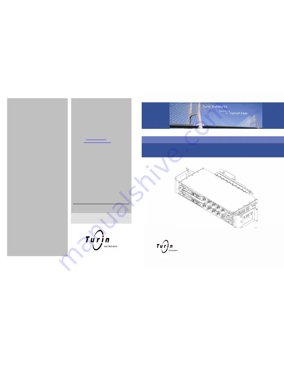
TE-206™ (VLX2006) Quick Install Guide


