Maintenance
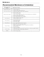
Check Fuel Filter and Tank
Service Interval: Before each use or daily
1.
Stop engine, wait for all moving parts to stop, and
remove key. Engage parking brake.
2.
Check the fuel filter and tank for leaks. See
Engine Owner's Manual.
Lubricate Grease Fittings
Note:
See chart for service intervals.
1.
Stop engine, wait for all moving parts to stop, and
remove key. Engage parking brake.
2.
Lubricate fittings with NLGI grade #2
multi-purpose gun grease.
Refer to the maintenance chart for fitting
locations and lubrication schedule.
Lubrication Chart
Fitting
Locations
Initial
Pumps
Number of
Places
Service
Interval
1. Front Caster
Pivots
*0
2
Yearly
2. Idler Pivot
1
1
Yearly
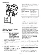
*See step 3 for special lubrication instructions on
the caster pivots.
3.
Lubricate caster pivots once a year. Remove hex
plug and cap. Thread grease zerk in hole and
pump with grease until it oozes out around top
bearing. Remove grease zerk and thread plug back
in. Place cap back on.
Check Condition of Belt
Service Interval: Every 40 hours
1.
Stop engine, wait for all moving parts to stop, and
remove key. Engage parking brake.
2.
Check the belt condition and tension.
Check Spark Plugs
Service Interval: Every 100 hours
Remove spark plugs, check condition and reset gaps,
or replace with new plugs. See Engine Owner's
Manual.
Wheel Hub–Slotted Nut
Torque Specification
Service Interval: After the first 100 hours
Every 500 hours thereafter
Torque the lug nuts on the wheel hub to 95 ft-lb (129
N-m).
Check Alternator
Service Interval: As required
20 Amp Regulated Alternator
The 20 amp regulated alternator system provides
AC current through two output leads to the
regulator-rectifier. The regulator-rectifier converts
the AC current to DC, and regulates current to the
battery. The charging rate will vary with engine RPM
and temperature.
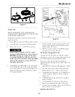
1.
Stator assembly (1) (Figure 35)
2.
Two YELLOW leads (2) from Stator.
3.
RED DC output lead (3) from connector.
4.
Connector (4)
5.
Two YELLOW AC input leads (5)
6.
Regulator-rectifier (6)
7.
RED DC output lead (7) to connector
Note:
Stator (1), regulator-rectifier (6) and fly-wheel
are NOT INTERCHANGEABLE with any other
charging system.
48
Содержание Z-SPRAY JUNIOR Series
Страница 1: ...Z SPRAY JUNIOR SERIES For Serial Nos 411 294 212 Higher Part No 4505 818 Rev A...
Страница 60: ...Notes 60...
Страница 61: ...Notes 61...
Страница 62: ...Service Record Date Description of Work Done Service Done By 62...
Страница 63: ...63...


