Tsino-Dynatron Electrical Technology (Beijing) Co., Ltd.
Chapter 4
Power On
Inspection Before Power On
4.1
Before the first time power on, please make sure the wiring is reliable and complete to prevent short circuit
and potential grounding hazards.
Cable Inspection
4.1.1
Table 4.1-1 Cable inspection
Number
Inspection item
1
Make sure the power supply inputs R/S/T/PE are properly connected, reliably insulated
from each other, as well as with correct phase sequence and undamaged cables.
2
Make sure the control power 24V/COM are properly connected, reliably insulated
from each other, as well as with correct electrodes and undamaged cables.
3
Make sure the motor power outputs U/V/W/PE are properly connected, reliably insulated
from each other, as well as with correct motor phase sequence and undamaged cables.
4
Make sure the braking resistor wiring B/P are properly connected, reliably insulated from
each other as well as from the housing, and with undamaged cables.
5
Make sure the motor brake outputs BK+/BK- are properly connected, reliably insulated
from each other, as well as with correct output electrodes and undamaged cables.
6
Conduct Continuity Test on the encoder cable to make sure the signals are properly
connected, reliably insulated from each other, as well as with correct wiring sequence and
undamaged cables.
7
Conduct Continuity Test on the communication cable and external IO cable to make sure
the signals are properly connected, reliably insulated from each other, as well as with
correct wiring sequence and undamaged cables.
Wiring Requirements
4.1.2
Table 4.1-2 Wiring requirements
Number
Inspection item
1
Make sure the power cable and ground wire outside the cabinet are routed straightly,
strapped separately with other cables and away from sharp parts of the machine.
2
The excess part of the ground wire and power cable should be cut off rather than coiled.
3
No cable should be overlapped on heating objects, such as radiator, braking resistors, etc.
4
The cable should have appropriate allowance at the turning points and not be tensioned.
5
The cable should be routed straightly and smoothly, wired uncrossed inside the cabinet,
while sorted and strapped outside the cabinet.
6
The power cable and the signal line as well as the feedback cable should be wired
separately, and strapped outside the cabinet separately.
7
Make sure both ends of each signal line are marked clearly (with labels).
8
Make sure all cable fixing screws are tightened.
9
Make sure all cable shielded layers are reliably grounded.
Power On
4.2
Power On
4.2.1
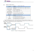
When the servo drive is powered on normally, the indicator status are as follows:
1
、
Close the control circuit switch, and indicator AXIS STA of the drive will flash green; If the drive has
established communication with the host, indicator EACT STA will turn solid green. If indicator AXIS
STA flashes red and green alternatively, or flashes red or turns solid red, it indicates that the servo has a
fault or alarm.
Note:
This is the safe power on sequence under normal circumstances. If this is not the case after the control circuit
switch is closed, then perform troubleshooting and close it again.
If an abnormal power-on is caused by a drive short circuit or opposite power electrodes connection, the drive
may have been damaged. In order to avoid potential hazards, please contact our technical support immediately.
29
Содержание EtherCAT CoolDrive RC Series
Страница 1: ...Updated on Update summary Updated version Version number D3 ...
Страница 17: ...Tsino Dynatron Electrical Technology Beijing Co Ltd Dimension Drawing of RC3 2 3 2 7 ...
Страница 18: ...Tsino Dynatron Electrical Technology Beijing Co Ltd Dimension Drawing of RC4 2 3 3 8 ...
Страница 19: ...Tsino Dynatron Electrical Technology Beijing Co Ltd 9 ...
Страница 20: ...Tsino Dynatron Electrical Technology Beijing Co Ltd Dimension Drawing of RC6 2 3 4 1 ...

