Tsino-Dynatron Electrical Technology (Beijing) Co., Ltd.
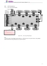
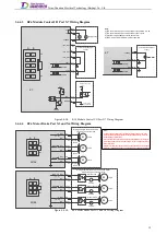
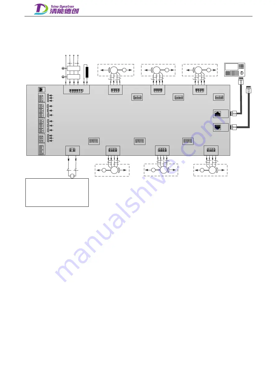
RC6 Wiring Diagram
3.4.4
3.4.4.1
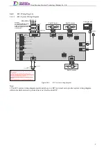
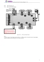
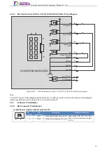
RC6 System Wiring Diagram
X41
U V W
M
Shaft 4 motor
X5
Shaft 4 motor brake
Shaft 4 encoder
PE
X6
X51
U V W
M
Shaft 5 motor
X5
Shaft 5 motor brake
Shaft 5 encoder
PE
X6
X61
U V W
M
Shaft 6 motor
X5
Shaft 6 motor brake
Shaft 6 encoder
PE
X6
X11
U
V
W
M
Shaft 1 motor
X4
Shaft 1 motor brake
Shaft 1 encoder
PE
X3
X21
U
V
W
M
Shaft 2 motor
X4
Shaft 2 motor brake Shaft 2 encoder
PE
X3
X31
U
V
W
M
Shaft 3 motor
X4
Shaft 3 motor brake
Shaft 3 encoder
PE
X3
X9
OUT
X8
IN
X1
R S T
PE
R S T
3
Φ
AC220V
Inlet filter
Input reactor
B P
X2
COM +24V
5
6
4
3
2
1
3 4
2
1
3 4
2
1
3 4
2
1
2 1
3
4
2 1
3
4
2 1
3
4
Shaft 1 encoder
Shaft 5 encoder
Shaft 4 encoder
Shaft 3 motor brake
Shaft 2 motor brake
Shaft 1 motor brake
Shaft 6 motor brake
Shaft 5 motor brake
Shaft 4 motor brake
PE
Circuit breaker
24VDC
Control power of drive
2
1
Note:
1. Do not connect the power supply to any other ports except port X1, which may
damage the product.
2. The input voltage of all ports should not exceed the allowed range.
3. The output voltage of the motor brake port is DC24V, and the maximum output
current is 1A. If its voltage is not DC24V, or the current carried by the motor brake
exceeds 1A, it must be controlled by an external relay.
4. Do not short connect the BK+ end of each shaft, which may incur danger. It is
recommended to connect the BK+ and BK- to the corresponding motor brakes
separately.
5. Make sure the wiring sequence is correct, the connection is secure and the
insulation is reliable before power on, otherwise it may damage the product.
Braking resistor
Resistance ≥
65
Ω
Upper (control)
system
EtherCAT
EtherCAT
X42
X52
X62
X12
X22
X32
Shaft 3 shaft
control I/O
Shaft 2 shaft
control I/O
Shaft 1 shaft
control I/O
Shaft 4 shaft
control I/O
Shaft 5 shaft
control I/O
Shaft 6 shaft
control I/O
A
B
5
1
A
B
5
1
A
B
5
1
A
B
5
1
A
B
5
1
A
B
5
1
X10
X3
X4-J3
X5-J6
X6
X7
A B
3
1
A B
5
1
A B
3
1
1
Shaft 3 encoder
Shaft 2 encoder
Shaft 6 encoder
Module control I/O
RS485
communication
debugging port
2
1
2
1
2
1
A B
2
1
2
1
2
1
A B
X4-J2
X4-J1
X5-J5
X5-J4
Circuit breaker
Description:
1. For single phase 220V
power supply input,
connect R and T terminals.
2. Before connecting to
single phase 220V power
supply, derate to 57% of
the rated power.
Figure 3.4-16.
RC6 System Wiring Diagram
Note:
1. The RC6 system wiring diagram mentioned above is a RC6 universal servo product system wiring diagram,
while robot dedicated servo products have no "shaft control I/O".
17
Содержание EtherCAT CoolDrive RC Series
Страница 1: ...Updated on Update summary Updated version Version number D3 ...
Страница 17: ...Tsino Dynatron Electrical Technology Beijing Co Ltd Dimension Drawing of RC3 2 3 2 7 ...
Страница 18: ...Tsino Dynatron Electrical Technology Beijing Co Ltd Dimension Drawing of RC4 2 3 3 8 ...
Страница 19: ...Tsino Dynatron Electrical Technology Beijing Co Ltd 9 ...
Страница 20: ...Tsino Dynatron Electrical Technology Beijing Co Ltd Dimension Drawing of RC6 2 3 4 1 ...

