6
DESIGN AND APPLICATION:
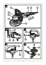
Fig.B 12.
Pin
The rotary buffer (hereinafter referred to as “buffer”) is a hand-held
power tool driven by a single-phase, commutator-type motor. It is
Fig.C 14.
Fixing screws with hex socket
equipped with an auxiliary handle that can be set in two positions.
15.
Allen (hex) key
Class II equipment (double insulation).
Fig.E 16.
Spindle
17.
Clamping nut
The buffer is designed for polishing metal surfaces, plastic products and
painted surfaces, including vehicles.
18.
Locking wrench
This electric tool is designed for jobs with medium intensity. It is not
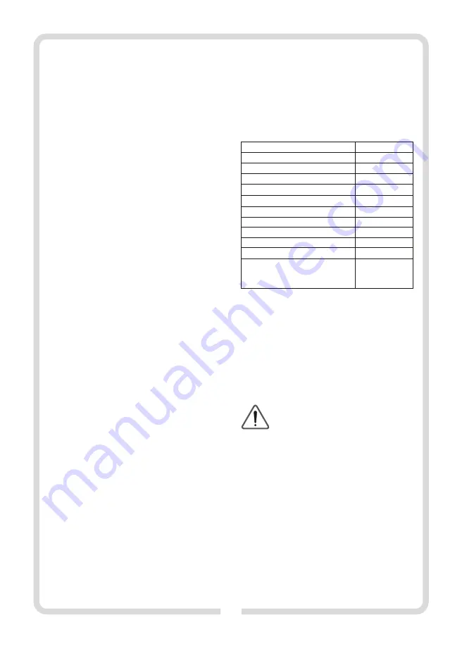
TECHNICAL DATA:
suitable for long-term operation under heavy duty conditions.
Do never
use the tool for applications that need use of professional
equipment.
BEFORE YOU START:
1. Make sure that electric parameters of the power voltage correspond
to parameters of the electric tool according to specifications on the
rating plate.
2. Make sure that the On/Off switch (
8
) of the electric tool is in its Off
THE SET CONTAINS:
position.
ź
Buffer - 1piece
3. While working with a power cord extension make sure that electric
ź
Auxiliary handle -1piece
parameters of the extension cable and cross-sections of its wires are
ź
Fixing screws with hexagonal socket - 2 pieces
appropriated for corresponding parameters of the electric tool. The
ź
Buffing disk - 1piece
extension cable must be fully uncoiled.
ź
Clamping nut -1piece
n
Installing the auxiliary handle
ź
Locking wrench -1piece
ź
Allen (hex) key -1piece
ź
Buffing pad -1piece
Transport
ation
case
-1 piece
NOTE:
For safety reasons always use its auxiliary handle during operation.
Warranty card -1 piece
Set the auxiliary handle (
4
) to align its pin (
12
) with groove (
13
) in the
-1 piece
power tool head body (fig.
B
).
Set fixing screws with hex socket (
14
) and turn them using the Allen key
DRAWING DESCRIPTION
(see pages 2-3)
:
(
15
). The auxiliary handle (
4
) can be installed in two ways as shown in
Fig.A
1.
Buffing disk
Fig.
C
and
D
, thus selecting the most comfortable setting.
2.
Arrow that indicates rotation direction
n
Installing and removing the buffing disk
3.
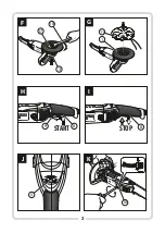
Spindle lock button
ź
Put the buffer with spindle (
16
) upwards. Place the buffing disk (
1
)
4.
Auxiliary handle
with its bottom protruding part onto the spindle pin to engage the
5.
Speed adjustment knob
disk on the spindle.
6.
Main handle
ź
Screw the clamping nut (
17
) onto the spindle to fix the disk securely
7.
Power cord
(fig.
E
).
8.
Switch
ź
Press the spindle lock button (
3
)
and tighten the locking nut exerting
9.
Locking lever
slight pressure using the locking wrench (
18
) provided, as during
10.
Brush-holder
operation the nut tightens up automatically. Following the above-
11.
Buffing pad
mentioned tip will result in avoiding damage to the reducer casing
Each application of the tool not in line with the intended use as specified
below is strictly forbidden and makes the warranty terms null and void.
The manufacturer shall not be held responsible for possible
consequential damage that may arise due to or in connection with such
application.
Any modifications of the tool by the user relieve the manufacturer from
responsibility for any damage and injuries to the user and the
surroundings.
Proper use cannot guarantee that no residual risk will occur. Due to the
design of the machine, the following risks may occur:
-
catching and entangling clothes by moving parts;
-
hearing impairment in case of long-term operation without ear
protectors;
-
eye injury resulted from throwing off buffed material particles;
- t
hrowing a machined part or pieces of a machined part
;
- emission dust hazardous for human health when works are carried out
in closed rooms (confined areas).
WARNING! Prior to installation and adjustment
always disconnect the plug from the mains socket.
ź
ź
ź
O
perating instruction
13.
Groove
Rated voltage
230-240
V
Rated frequency
50
Hz
Power consumption
130
0
W
Max
. s
peed
under no-load conditions
rpm
33
00
Max. disk diameter
180
mm
Spindle thread
M14
Equipment class
II
Power cord length
5
m
Weight
3,6
к
g
Sound pressure level (LpA)
K=3
dB(A)
dB(A)
93
Sound power level (LwA)
K=3
dB(A)
dB(A)
104
Vibration level according to EN 60745-1:2009
2
(measuring tolerance
K=
1
,
5m/s
)
polishing the surface
a
h AG
6
,
972
2
m/s
Содержание TMA1300K
Страница 2: ...2 A 1300W 1 2 3 4 5 7 8 9 10 11 B 12 13 C D 14 14 15 4 15 4 E 17 1 16 13 00 W 6 4...
Страница 3: ...STOP 1 2 2 8 1300W 9 START 1 2 8 1300W 3 F 18 3 H G I 17 11 1 13 00 W 13 00 W 1300W K J 10 5 6 mm...
Страница 14: ...RCD TMA1300K 14...
Страница 15: ...15 a a...
Страница 16: ...16...
Страница 18: ...18 n n 8 8 9 1 9 4 H 12 13 2 8 B 14 15 4 8 D n 16 1 1 2 I 17 3 18 n J 600 3300 8 5 1 6 F 6 1 n n G 1 11 n 3...
Страница 19: ...19 n 10 5 7 n K 6 34 03 228 PROFIX...
Страница 36: ......


