1.
Fault indication and messages
Faults are displayed at different positions:
■
Status LEDs on the DC-DC module.
■
Status LEDs on the TruConvert System Control.
■
On the web-based user interface.
■
Via the Modbus.
1.1
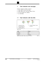
Fault indication with the LEDs
1
Front side TruCon-
vert DC series 1000
2
Rear side TruCon-
vert DC series 1000
3
TruConvert System Control
front side
Status LEDs
Fig. 9-1
LED
Errors
1 (green)
off
2 (yellow)
off
3 (red)
Flashing
Display of the status LEDs in the event of a fault
Tab. 9-1
9
‐
2
Fault indication and messages
2020-07-01
A67-0140-00.BKen-0
01-05
Содержание TruConvert DC 1000 Series
Страница 1: ...Operator s manual TruConvert DC series 1000 TruConvert System Control TruConvert Modular...
Страница 2: ......
Страница 6: ...II Good to know 2020 07 01 A67 0140 00 BKen 0 01 05...
Страница 36: ...3 12 Technical data dependent on device variant overview 2020 07 01 A67 0140 00 BKen 0 01 05...
Страница 38: ...7 Ethernet 4 10 8 RS 485 4 11 4 2 Interfaces 2020 07 01 A67 0140 00 BKen 0 01 05...
Страница 40: ...Fig 4 3 4 4 Protective earth TruConvert DC series 1000 2020 07 01 A67 0140 00 BKen 0 01 05...
Страница 48: ...4 12 RS 485 2020 07 01 A67 0140 00 BKen 0 01 05...
Страница 54: ...5 6 CSA certification 2020 07 01 A67 0140 00 BKen 0 01 05...
Страница 106: ...16 State diagram State machine Fig 7 19 7 38 State diagram 2020 07 01 A67 0140 00 BKen 0 01 05...


