background image

EN

9

pedestal fan TVE 24 S

Operation

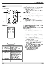
Operating elements

18

19

20

21

22

Remote control

18

19

20

23

No.

Designation

Meaning

18

SPEED

 button

Selecting the fan stage

19

Oscillation

 button Activating and deactivating the

oscillation function

20

ON/OFF

 button

Switching the device on and off

21

Segment display

• Indication of the number of hours of
the activated timer (1 h to 8 h)
• Indication of the fan stage (1–8):
Stage 1 = low fan speed
Stage 4 = medium fan speed
Stage 8 = high fan speed

22

TIMER

 indication Indication of the timer function

23

TIMER

 button

Switching the timer function on and
off

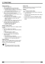
Switching the device on

Once you have completely installed the device as described in
the chapter Assembly and start-up, you can switch it on.

1. Press the 

ON/OFF

 button (20).

ð

An acoustic signal is emitted and the device starts up at
fan stage 1.

Setting the fan stage

The fan can be set to eight stages while in operation.

1. Repeatedly press the 

SPEED

 button (18) until the desired

fan stage is shown on the segment display (21).

ð

The fan operates at the selected fan stage.

Setting the timer

The timer has two modes of operation:

automatic switch-on upon expiry of a preset number of
hours

automatic switch-off upon expiry of a preset number of
hours

The number of hours of the timer can be between 1 and 8 and
can be adjusted in increments of 1 h.
It can be activated both during operation and in standby mode.

Automatic switch-on

ü

The device is switched off.

1. Press the 

TIMER

 button (23) on the remote control to

activate the timer.

ð

The 

TIMER

 indication (22) flashes for approx. 5 s.

ð

The segment display (21) indicates a "1", meaning that
one hour is left until automatic switch-on.

2. Press the 

TIMER

 button (23) again to select the desired

number of hours until automatic switch-on.

ð

The segment display (21) indicates the number of hours
until automatic switch-on.

3. Wait for 5 seconds to confirm the setting.

ð

The 

TIMER

 indication (22) is illuminated. The segment

display (21) indicates the number of hours until
automatic switch-on.

ð

After the predefined time, the device switches itself on.

4. To delete the setting, press the 

TIMER

 button (23)

repeatedly until the segment display indicates a "0".

5. Wait for 5 seconds to confirm the setting.

ð

The 

TIMER

 indication (22) disappears.

ð

The timer has been deactivated.

Содержание 1050000214

Страница 1: ...TRT BA TVE24S TC220614TTRT01 004 EN TVE 24 S EN OPERATING MANUAL PEDESTAL FAN ...

Страница 2: ... the immediate vicinity of the device or its site of use Warning Read all safety warnings and all instructions Failure to follow the warnings and instructions may result in electric shock fire and or serious injury Save all warnings and instructions for future reference This appliance can be used by children aged from 8 years and above and persons with reduced physical sensory or mental capabiliti...

Страница 3: ...ot be used together Insert the batteries into the battery compartment according to the correct polarity Remove discharged batteries from the device Batteries contain materials hazardous to the environment Dispose of the batteries according to the national regulations Remove the batteries from the remote control if you will not be using the device for a longer period of time Never short circuit the...

Страница 4: ...ld onto the mains plug while pulling the power cable out of the mains socket 3 Do not reconnect a defective device to the mains Information about the device Device description The pedestal fans of the TVE S series are suitable for indoor air circulation The device TVE 24 S comes with the following features 8 speed levels Height adjustability Inclination angle of the fan head vertically adjustable ...

Страница 5: ...being used observe the following storage conditions Store the device in a dry location and protected from frost and heat If required use a cover to protect the device from invasive dust Place no further devices or objects on top of the device to prevent it from being damaged Remove the batteries from the remote control Assembly and start up Scope of delivery 1 x Device TVE 24 S 1 x Remote control ...

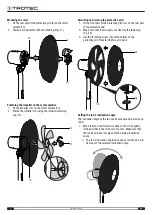
Страница 6: ...ive grid 14 on the rear part of the protective grid 2 Make sure that the two parts are fixed by the fastening clip 15 3 Use the fastening screw 16 at the bottom of the protective grid to fasten the two grid parts 14 15 16 Setting the fan s inclination angle The inclination angle of the fan can be manually adjusted by up to 30 1 Move the fan head forward or back so that it is slightly inclined eith...

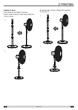
Страница 7: ...S Adjusting the height The fan height can be adjusted to 3 positions Remove one part of the pole to adjust the fan height from 130 cm to 100 cm 1 2 Remove two parts of the pole to adjust the fan height from 130 cm to 70 cm 3 4 ...

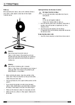
Страница 8: ...stomer service Only put up the device in an upright stable position on firm ground Do not create tripping hazards when laying the power cable or other electric cables especially when positioning the device in the middle of the room Use cable bridges Make sure that extension cables are completely unrolled Make sure that no curtains or other objects interfere with the air flow Inserting batteries in...

Страница 9: ...lected fan stage Setting the timer The timer has two modes of operation automatic switch on upon expiry of a preset number of hours automatic switch off upon expiry of a preset number of hours The number of hours of the timer can be between 1 and 8 and can be adjusted in increments of 1 h It can be activated both during operation and in standby mode Automatic switch on ü The device is switched off...

Страница 10: ... ventilation ü The device is switched on and operating 1 Press the Oscillation button 19 to activate the oscillation function ð The oscillation function is activated ð The fan head rotates to and fro by up to 80 2 Press the Oscillation button 19 to deactivate the oscillation function ð The oscillation function is deactivated ð The device stops oscillation at the desired position and continues to r...

Страница 11: ...specialist electrical company or to Trotec for repair Maintenance Note All service activities other than those specified in the maintenance table may only be performed by a specialist company authorized by Trotec Activities required before starting maintenance Warning of electrical voltage Do not touch the mains plug with wet or damp hands Switch the device off Hold onto the mains plug while pulli...

Страница 12: ...from your municipality or local administration You can also find out about other return options that apply for many EU countries on the website https hub trotec com id 45090 Otherwise please contact an official recycling centre for electronic and electrical equipment authorised for your country The separate collection of waste electrical and electronic equipment aims to enable the re use recycling...

Страница 13: ...Trotec GmbH Grebbener Str 7 D 52525 Heinsberg 49 2452 962 400 49 2452 962 200 info trotec com www trotec com ...

Отзывы: