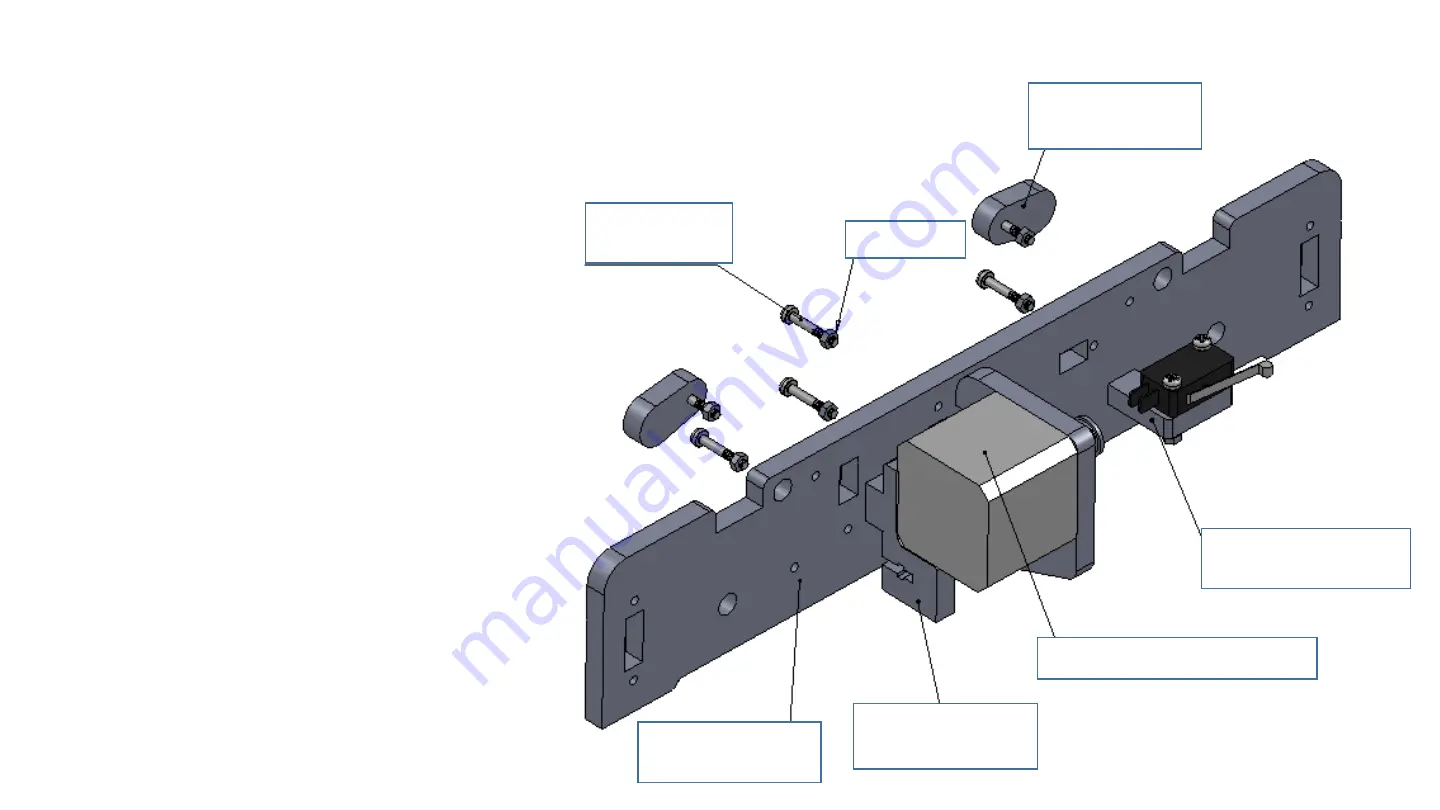
Step 3 Assemble Base Frame Holder_Back
Y-axis motor assembly
Sliding rod
Restriction*2
M3*20mm
screws
Y-axis limit
switch assembly
Y-axis motor
holder
Base frame
holder_Back
M3 nuts
As the picture, put two of the Sliding rod
Restriction in front of the base frame
holder (back). locking with two M3*20mm
screws & nuts.
Put the limit switch and holder assembly
on the base frame holder, locking with one
M3*20mm screw & nut.
Put Y-axis motor holder on base frame
holder ,locking with one M3*20mm screw
& nut.
Put Y-axis motor assembly on base frame
holder, locking with three M3*20mm
screws & nuts.
Содержание P802M
Страница 1: ......
Страница 28: ...Installation Finished ...


