background image

73

1

2

3

4

5

6

7

8

9

8 – Возможность использования сетевых подключений

Примечания: Описанные сетевые подключения предназначены для осуществления дополнительных функций. Они не являются 

критическими для обеспечения работы системы ИБП. 

8-1 Сетевая карта 

8-2 Порт EPO (аварийного отключения питания) 

8-3 Серийный порт RS-232

В комплект поставки системы ИБП входит сетевая карта локальной сети, которая дает пользователям возможность использовать  

коммуникационный интерфейс для локальной сети Ethernet в целях осуществления дистанционного управления и контроля системы 

ИБП. Дополнительная информация содержится в пакете сопроводительных документов для сетевой карты. 

Примечание: При 

использовании серийного порта RS-232 системы ИБП сетевую карту следует удалить.

Закорачивание выводов EPO приводит в действие функцию EPO (аварийного отключения питания), которая обеспечивает аварийное 

отключение системы ИБП. 

Примечание: Перед использованием серийного порта RS-232 системы ИБП следует удалить сетевую карту. 

Для подсоединения серийного порта RS-232 системы ИБП к серийному порту RS-232 компьютера используйте входящий в комплект 

поставки серийный кабель RS-232 (DB9). Для дистанционного управления и контроля системы ИБП установите на компьютер 

входящее в комплект поставки программное обеспечение (Вы найдете требования к системе, инструкции по установке ПО и 

дополнительную информацию о программе в сопроводительной документации к ПО).

Настройки коммуникационного интерфейса RS-232:

Скорость передачи в Бодах 

2400 бод в секунду 

Количество бит данных

8 бит

Стоп-бит 

1 бит

Контроль по четности 

Отсутствует

Разводка контактов RS-232: 

Пин 3: RS-232 Rx 


Пин 2: RS-232 Tx 


Пин 5: земля 

Содержание SmartOnline SU10KRT3/1X

Страница 1: ...atures 4 4 Mounting 5 4 1 Unpacking 5 4 2 Placement 6 4 3 Mounting Rack 6 4 4 Mounting Tower 7 5 Wiring 7 5 1 Wiring Preparation 7 5 2 Terminal Block Diagram 7 5 3 Electrical and Cable Data 8 5 4 AC Input Output Wiring Instructions 8 5 5 External Battery Pack Connection 9 6 Standard Operation 10 6 1 Control Panel Features 10 6 2 Control Panel Error Codes 11 6 3 Normal Mode Startup 12 6 4 Battery M...

Страница 2: ...ntilation openings of the UPS system or otherwise impede the airflow from the front to the rear of the UPS system Do not place any object on the UPS system especially containers of liquid Spilling liquids on the unit or dropping foreign objects into the unit will invalidate the warranty Install the unit in a location where contact with people is minimized Keep all recorded magnetic media such as d...

Страница 3: ... damage the UPS system and create a risk of personal injury and property damage Wiring should be performed by trained qualified electricians only Battery Warnings Allow batteries to charge uninterrupted for 12 hours after installation There are no user serviceable parts inside the UPS system Battery service or replacement must be performed or supervised by qualified service personnel familiar with...

Страница 4: ...e network card in order to use the RS 232 port B Settings Switch for Parallel Redundancy Operation C CAN Bus Connection Ports for Parallel Redundancy Operation D Cooling Fans E External Battery Pack DC Cable Connector F Utility Input Breaker G Ventilation Openings H Input Output Terminal Block I EPO Emergency Power Off Connection J Network Card Note One end of the Adapter Cable connects to the Pow...

Страница 5: ... unit Inspect the unit carefully prior to installation If anything appears to be damaged contact Tripp Lite for service Retain the packing materials for future use Packing List 1 UPS Power Module 1 External Battery Pack 1 UPS System Owner s Manual 1 Communication Software Kit 1 RS 232 Cable 1 UPS System Hardware Kit See below for detail 1 Parallel Redundancy Hardware Kit See Section 7 Parallel Red...

Страница 6: ...osure for a solution For further mounting instructions see the Owner s Manual for Tripp Lite Model No BP240V10RT3U 4 Post Mounting Procedure Note The mounting procedure is identical for the external battery pack and the UPS power module Mount the external battery pack first then repeat the procedure for the UPS power module The external battery pack should be mounted in the lowest available rack s...

Страница 7: ...nd face outward 4 Mounting continued 5 Wiring DANGER LETHAL HIGH VOLTAGE HAZARD All wiring should be performed by a qualified electrician in accordance with the warnings in this manual and all applicable electrical and safety codes Incorrect wiring may cause serious personal injury and property damage Read study and understand the warnings listed in Section 2 Important Safety Instructions before p...

Страница 8: ...lock 2 Route the AC input output wiring through cable sleeves and route the cable sleeves through the knockouts in the terminal block cover A2 Each input output wire should terminate with a ring terminal 3 Connect the ring terminal for each input output cable to the appropriate input output terminals Tighten the terminals with at least 2 60 N m of torque 4 Secure the input output cable bundles to ...

Страница 9: ...system 1 Switch the external battery pack s DC breaker to the OFF position 2 Remove the terminal covers from the UPS power module s external battery pack DC cable connector and the external battery pack s UPS power module DC cable connector Retain the screws removed from the terminal covers 3 Connect one end of the DC cable C2 to each of the DC terminals exposed in the previous step Use the screws...

Страница 10: ... in economy mode 6 Fault LED This red LED illuminates when UPS system experiences a fault or other abnormal condition If the condition persists after restarting the UPS system refer to Section 9 Troubleshooting 7 ON Button This button controls these separate functions UPS System Power ON To turn on the UPS system press this button for approximately one second until the UPS system beeps then releas...

Страница 11: ...of temperature voltage amperage level percentage and frequency Indicates the category being measured line load battery EPO Emergency Power Off Code Description Er05 Battery Weak or Dead Er06 Output Short Circuit Er10 Inverter Overcurrent Er11 UPS Overheat Er12 UPS Output Overload Er14 Fan Error Er15 Wrong Procedure Used to Enter Maintenance Mode Er16 Error in Parallel System Output Parameters Er17...

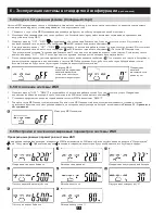
Страница 12: ...l and the battery charger begins to charge the external battery pack 8 Press the ON button for approximately 3 seconds then release it The UPS will beep twice and the LCD screen will change from B to C 9 The UPS system will perform another self test and the LCD screen will change from C to D and switch to battery mode for approximately 4 seconds If the self test is successful the LCD screen will c...

Страница 13: ...e elapsed you will need to repeat the previous step 5 The UPS system will run a self test and display H again Battery mode startup is successful and connected equipment will operate until the battery is depleted or until pre defined shutdown parameters have been reached 1 Press the OFF button for approximately 5 seconds then release it The inverter output will turn off and the LCD screen will show...

Страница 14: ...ately three seconds until the buzzer sounds twice then release the buttons Except for buzzer Q1 Q2 and self test R1 R2 all other default settings may now be changed by pressing the Previous Change Setting button After changing settings press the Enter button to save all changes AA To cancel all changes press and hold the OFF button for five seconds then release the button BB Buzzer ON Bypass Accep...

Страница 15: ...supply circuit is securely grounded Start up Procedure 1 Position the UPS systems as specified above 2 Connect the parallel communication cables C1 C2 to the Ring loop at a maximum length of 7 m Secure the cables with the parallel communication brackets B1 3 Arrange the power cables and the control signal cables according to UPS type Make sure that all circuit breakers at the input and output ends...

Страница 16: ...orting the EPO terminals activates the EPO emergency power off function which provides emergency shutdown of the UPS system Note The network card must be removed in order to use the UPS system s RS 232 port Use the included RS 232 DB9 serial cable to connect the UPS system s RS 232 serial port to a computer s RS 232 serial port Install the included software on the computer in order to monitor and ...

Страница 17: ...lt LED Er16 Er27 All parallel UPS parameters except ID number must be same Adjust the parameters Fault LED Er21 Reconnect the RJ45 cable or set a UPS with ID 1 Fault LED Other Error Code Have a qualified electrician check the AC supply circuit and wiring then restart the UPS system If the problem persists contact Tripp Lite for service UPS fails to offer battery backup or backup time is much short...

Страница 18: ... utility power source Next disconnect all equipment The UPS system must be stored in a clean secure environment with a temperature less than 40 C and a relative humidity less than 90 non condensing Note If the UPS system remains off for an extended period of time it should be turned on periodically to allow the batteries to recharge The UPS system should be turned on and the batteries should be re...

Страница 19: ... you specific legal rights and you may have other rights which vary from jurisdiction to jurisdiction Tripp Lite 1111 W 35th Street Chicago IL 60609 USA WARNING The individual user should take care to determine prior to use whether this device is suitable adequate or safe for the use intended Since individual applications are subject to great variation the manufacturer makes no representation or w...

Страница 20: ... 23 4 Montaje 24 4 1 Desembalaje 24 4 2 Colocación 25 4 3 Montaje Rack 25 4 4 Montaje Torre 26 5 Cableado 26 5 1 Preparación del cableado 26 5 2 Diagrama del bloque de terminales 26 5 3 Datos eléctricos y de los cables 27 5 4 Instrucciones del cableado de entrada salida de CA 27 5 5 Conexión del módulo de baterías externas 28 6 Funcionamiento estándar 29 6 1 Características del panel de control 29...

Страница 21: ...istema de UPS No coloque ningún objeto sobre el UPS especialmente contenedores de líquido El derrame de líquidos sobre la unidad o dejar caer objetos ajenos en la unidad invalidará la garantía Instale la unidad en un lugar donde el contacto con las personas sea mínimo Mantenga todos los medios magnéticos grabados como disquetes cintas y cartuchos a una distancia mínima de 60 cm del sistema de UPS ...

Страница 22: ...etan la fase o polaridad correctas el sistema de UPS se dañará y creará un riesgo de lesión personal y daño a la propiedad El cableado sólo deben realizarlo electricistas capacitados y calificados Advertencias sobre las baterías Permita que las baterías se carguen en forma ininterrumpida durante 12 horas después de la instalación Dentro del sistema de UPS no hay partes que el usuario pueda reparar...

Страница 23: ...a de UPS A Puerto RS 232 Nota quite la tarjeta de red para poder utilizar el puerto RS 232 B Interruptor de configuración para el funcionamiento de redundancia paralela C Puertos de conexión de bus CAN para el funcionamiento de redundancia paralela D Ventiladores E Conector de cable CC para módulo de baterías externas F Disyuntor de entrada de la red pública G Aberturas de ventilación H Bloque de ...

Страница 24: ...go parece estar dañado comuníquese con el servicio técnico de Tripp Lite Guarde los materiales de embalaje para utilizarlos en el futuro Lista de embalaje 1 módulo de alimentación UPS 1 módulo de baterías externas 1 manual del propietario del sistema de UPS 1 kit de software de comunicación 1 cable RS 232 1 kit de herramientas del sistema de UPS consulte a continuación los detalles 1 kit de herram...

Страница 25: ...ctions see the Owner s Manual for Tripp Lite Model No BP240V10RT3U 4 Procedimiento después del montaje Nota El procedimiento de montaje es idéntico para los módulos de baterías externas y el módulos eléctrico UPS Coloque primero el módulo de baterías externas luego repita el procedimiento para el módulo eléctrico UPS El módulo de baterías externas debe montarse en el espacio de rack más bajo dispo...

Страница 26: ... ALTA TENSIÓN Todo el cableado debe ser realizado por un electricista calificado de acuerdo con las advertencias de este manual y los códigos de seguridad y eléctricos correspondientes El cableado incorrecto puede causar graves lesiones personales y daño a la propiedad Lea estudie y entienda las advertencias enumeradas en la sección 2 Instrucciones de seguridad importantes antes de continuar 5 1 P...

Страница 27: ... entrada salida a través de fundas para cables y guíe a estas a través de los accesos de la cubierta del bloque de terminales A2 Cada cable de entrada salida debe terminar con un anillo terminal 3 Conecte el anillo terminal de cada cable de entrada salida en la terminal de entrada salida correspondiente Apriete las terminales con un torque mínimo de 2 60 N m 4 Fije los manojos de cables de entrada...

Страница 28: ...ntor de CC del módulo de baterías externas en la posición APAGADO 2 Quite las cubiertas de las terminales del conector del cable de CC del módulo de baterías externas para módulo eléctrico UPS y el conector del cable de CC del módulo eléctrico UPS para el módulo de baterías externas Retenga los tornillos que quitó de las cubiertas de las terminales 3 Conecte un extremo del cable de CC C2 a cada un...

Страница 29: ...a 6 LED de falla Este LED rojo se ilumina cuando el sistema de UPS falla o existe otra condición anormal Si la condición persiste después de reiniciar el sistema de UPS consulte la sección 9 Resolución de problemas 7 Botón ENCENDIDO Este botón controla las siguientes funciones independientes ENCENDIDO del sistema de UPS Para encender el sistema de UPS presione este botón durante aproximadamente un...

Страница 30: ...peratura voltaje amperaje nivel porcentaje y frecuencia Indica la categoría que se mide línea carga batería EPO Apagado de emergencia Código Descripción Er05 Batería débil o agotada Er06 Cortocircuito en la salida Er10 Sobretensión del inversor Er11 UPS sobrecalentado Er12 Sobrecarga de la salida del UPS Er14 Error del ventilador Er15 Procedimiento erróneo utilizado para ingresar al Modo de manten...

Страница 31: ...ma de UPS fue correcto y el cargador de batería comienza a cargar el módulo de baterías externas 8 Presione el botón ENCENDIDO durante aproximadamente 3 segundos y luego suéltelo El UPS emitirá dos pitidos y la pantalla LCD cambiará de B a C 9 El sistema de UPS realizará otro autotest luego la pantalla LCD cambiará de C a D y luego cambiará a modo batería durante aproximadamente 4 segundos Si el a...

Страница 32: ...PS ejecutará un autotest y volverá a mostrar la pantalla H El arranque en modo batería es correcto y los equipos conectados funcionarán hasta que la batería se agote o hasta que se alcancen los parámetros de apagado predefinidos 1 Presione el botón APAGADO durante aproximadamente 5 segundos y luego suéltelo Se apagará la salida del inversor y la pantalla LCD mostrará B 2 Apague el disyuntor de ent...

Страница 33: ...asta que el zumbador suene dos veces luego suelte los botones Excepto por las configuraciones del zumbador Q1 Q2 y del autotest R1 R2 ahora puede cambiar el resto de las configuraciones predeterminadas presionando el botón Anterior Cambiar configuración Después de cambiar las configuraciones presione el botón Intro para guardar los cambios AA Para cancelar todos los cambios presione y mantenga el ...

Страница 34: ...anque 1 Coloque los sistemas de UPS como se indicó anteriormente 2 Conecte los cables de comunicación paralela C1 C2 al bucle en Anillo para obtener la longitud máxima de 7 m Asegure los cables con los soportes para comunicación paralela B1 3 Acomode los cables de alimentación y los cables de señal de control de acuerdo con el tipo de UPS Asegúrese de que todos los disyuntores en los extremos de e...

Страница 35: ...a la función EPO apagado de emergencia que proporciona el apagado de emergencia del sistema de UPS Nota Para utilizar el puerto RS 232 del sistema de UPS debe quitar la tarjeta de red Utilice el cable serial RS 232 DB9 incluido para conectar el puerto serial RS 232 del sistema de UPS a un puerto serial RS 232 de una computadora Para monitorear y controlar el sistema de UPS instale en la computador...

Страница 36: ...úmero de ID deben ser los mismos Ajuste los parámetros LED de falla Er21 Vuelva a conectar el cable RJ45 o establezca un UPS con ID 1 LED de falla Otro código de error Llame a un electricista calificado para que verifique el circuito y cableado de suministro de CA luego reinicie el sistema de UPS Si el problema continúa comuníquese con Tripp Lite para obtener servicio técnico El UPS no proporciona...

Страница 37: ...tema de UPS luego desconecte la entrada del sistema de UPS de la fuente de alimentación de CA de la red pública A continuación desconecte todos los equipos El sistema de UPS se debe almacenar en un ambiente limpio y seguro con temperaturas menores a los 40 ºC y una humedad relativa menor al 90 sin condensación Nota Si el sistema de UPS permanece apagado durante un período de tiempo prolongado se l...

Страница 38: ...onder en su caso Esta garantía le otorga derechos legales específicos y usted puede tener otros derechos que varían de una jurisdicción a otra Tripp Lite 1111 W 35th Street Chicago IL 60609 USA ADVERTENCIA Antes de usar este aparato cada usuario debe ocuparse de determinar si es apto adecuado o seguro para el uso que pretende darle Dado que cada aplicación está sujeta a grandes variaciones el fabr...

Страница 39: ...4 1 Déballage 43 4 2 Mise en place 44 4 3 Montage rack 44 4 4 Montage tour 45 5 Câblage 45 5 1 Préparation des câbles 45 5 2 Schéma des bornes 45 5 3 Données électriques et câbles 46 5 4 Consignes de câblage entrée sortie c a 46 5 5 Connexion du pack batterie externe 47 6 Fonctionnement standard 48 6 1 Caractéristiques du panneau de contrôle 48 6 2 Codes d erreur du panneau de contrôle 49 6 3 Déma...

Страница 40: ... adéquate de ce système Ne pas bloquer couvrir ou insérer des objets dans les ouvertures de ventilation externe du système UPS ni bloquer l écoulement d air à l avant ou à l arrière du système Ne pas poser d objet sur le système ASI en particulier des récipients contenant un liquide Des liquides versés sur l unité ou des objets étrangers introduits dans l unité rendront la garantie nulle Installez...

Страница 41: ...SI avec un risque potentiel de dommages matériels et personnels Le câblage doit être réalisé par des électriciens qualifiés et formés uniquement Avertissements relatifs aux batteries Laissez les batteries se charger sans interruption pendant 12 heures après l installation Le système ASI ne contient aucune pièce pouvant être réparée par l utilisateur L entretien ou le remplacement des batteries doi...

Страница 42: ...I A Port RS 232 NB retirez la carte réseau pour utiliser le port RS 232 B Interrupteur de réglage pour un fonctionnement en mode parallèle redondant C Ports de connexion bus CAN pour fonctionnement en mode parallèle redondant D Ventilateurs de refroidissement E Connecteur de câble c c pour pack batterie externe F Disjoncteur d alimentation secteur G Ouvertures de ventilation H Plaque à bornes entr...

Страница 43: ...neusement l unité avant de l installer Si un élément semble endommagé contactez Tripp Lite pour un entretien Conservez les matériaux d emballage pour une utilisation ultérieure Liste de colisage 1 Module d alimentation ASI 1 Pack batterie externe 1 Guide d utilisation du système ASI 1 Kit logiciel de communication 1 Câble RS 232 1 Kit matériel du système ASI voir détails ci dessous 1 Kit matériel ...

Страница 44: ...ur trouver une solution For further mounting instructions see the Owner s Manual for Tripp Lite Model No BP240V10RT3U Procédure de montage avec 4 montants NB La procédure de montage est identique pour le pack batterie externe et le module d alimentation ASI Montez d abord le pack batterie externe puis répétez la procédure pour le module d alimentation ASI Le pack batterie externe doit être monté d...

Страница 45: ... outward 4 Montage suite 5 Câblage DANGER HAUTE TENSION DANGER DE MORT Tous les câblages doivent être effectués par un électricien qualifié en respectant les avertissements de ce manuel et tous les codes électriques et de sécurité en vigueur Un mauvais câblage peut causer des dommages personnels et matériels graves Veuillez lire étudier et comprendre les avertissements figurant en Section 2 Consig...

Страница 46: ...miner par une cosse à anneau 3 Connectez la cosse à anneau de chaque câble d entrée sortie à la borne d entrée sortie appropriée Serrez les bornes avec un couple de serrage d au moins 2 60 N m 4 Fixez les faisceaux de câbles d entrée sortie au plateau de fixation des câbles à l aide des attaches de montage fournies A3 5 Utilisez des vis à tête cylindrique large M3 S5 pour fixer le couvercle de la ...

Страница 47: ...interrupteur c c du pack batterie externe en position OFF 2 Retirez les cache bornes du connecteur c c du pack batterie externe du module d alimentation ASI et du connecteur c c du module d alimentation ASI du pack batterie externe Conservez les vis retirées du cache bornes 3 Connectez une extrémité du câble c c C2 à chacune des bornes c c exposées à l étape précédente Utilisez les vis que vous av...

Страница 48: ...ionne dans des conditions anormales Si cet état persiste après le redémarrage du système ASI consultez la Section 9 Résolution des problèmes 7 Bouton ON Ce bouton contrôle les diverses fonctions suivantes Mise sous tension du système ASI Pour allumer le système ASI appuyez sur ce bouton pendant environ une seconde jusqu à ce que vous entendiez un bip puis relâchez ce bouton Mise en sourdine de l a...

Страница 49: ...ant de niveau pourcentage et de fréquence Indique la catégorie en train d être mesurée ligne charge batterie EPO Coupure d alimentation d urgence Code Description Er05 Batterie faible ou morte Er06 Court circuit de sortie Er10 Surintensité de l onduleur Er11 Surchauffe de l ASI Er12 Surcharge de sortie ASI Er14 Problème du ventilateur Er15 Mauvaise procédure utilisée pour accéder au mode Maintenan...

Страница 50: ...ASI est réussi et le chargeur de la batterie commence à charger le pack batterie externe 8 Appuyez sur le bouton ON pendant environ 3 secondes puis relâchez le L ASI va biper deux fois et l écran LCD va passer de B à C 9 Le système ASI va effectuer un autre auto test et l écran LCD va passer de C à D et passer en mode batterie pendant environ 4 secondes Si l auto test est réussi l écran LCD va pas...

Страница 51: ...ystème ASI va effectuer un auto test et afficher à nouveau H Le démarrage en mode batterie est réussi et l appareil connecté fonctionne jusqu à ce que la batterie soit complètement déchargée ou jusqu à ce que les paramètres d arrêt prédéfinis soient atteints 1 Appuyez sur le bouton OFF pendant environ 5 secondes puis relâchez le L onduleur va biper deux fois et l écran LCD va afficher B 2 Mettez l...

Страница 52: ...e deux fois puis relâchez ces deux boutons À l exception de l alarme Q1 Q2 et de l auto test R1 R2 tous les autres réglages par défaut peuvent être modifiés en appuyant sur le bouton Réglage précédent Changement de réglage Après avoir changé les réglages appuyez sur le bouton Enter pour enregistrer tous ces changements AA Pour annuler tous les changements appuyez sur le bouton OFF et maintenez le ...

Страница 53: ...Positionnez le système ASI comme spécifié ci dessus 2 Connectez les câbles de communication parallèle C1 C2 à la boucle Anneau avec une longueur maximale de 7 m Fixez les câbles aux plaques de communication parallèle B1 3 Arrangez les câbles électriques et les câbles de signaux de contrôle selon le type d ASI Assurez vous que tous les interrupteurs de circuit sont sur OFF aux extrémités d entrée e...

Страница 54: ...active la fonction EPO Emergency Power Off pour une coupure d alimentation d urgence du système ASI NB La carte réseau doit être retirée pour utiliser le port RS 232 du système ASI Utilisez le câble série RS 232 DB9 inclus pour connecter le port série RS 232 du système ASI au port série RS 232 d un ordinateur Installez le logiciel inclus sur l ordinateur de façon à pouvoir suivre et contrôler le s...

Страница 55: ...paramètres ASI parallèle à l exception du numéro d ID doivent être les mêmes Ajustez ces paramètres LED de panne Er21 Reconnectez le câble RJ45 ou réglez un ASI avec ID 1 LED de panne Autre code d erreur Demandez à un électricien qualifié de vérifier le circuit et les câblages d alimentation c a puis redémarrez le système ASI Si ce problème persiste contactez Tripp Lite pour une révision L ASI ne ...

Страница 56: ... du système ASI depuis la source d alimentation secteur c a Ensuite déconnectez tous les équipements Le système ASI doit être stocké dans un environnement propre sûr à une température inférieure à 40 C et à une humidité relative inférieure à 90 sans condensation NB Si le système ASI reste éteint pendant une longue période de temps il devra être allumé périodiquement pour permettre aux batteries de...

Страница 57: ...t peut être pas à votre cas Cette garantie vous donne des droits juridiques spécifiques et vous disposez peut être d autres droits en fonction de votre juridiction Tripp Lite 1111 W 35th Street Chicago IL 60609 États Unis AVERTISSEMENT L utilisateur individuel devra déterminer avant d utiliser cet appareil si celui ci est approprié adapté et sûr pour l utilisation prévue Certaines applications ind...

Страница 58: ...е 63 4 3 Сборка стоечный вариант 63 4 4 Сборка вертикальный вариант 64 5 Электромонтажные работы и подключение 64 5 1 Подготовка к проведению электромонтажных работ и подключения 64 5 2 Схема блока выводов 64 5 3 Параметры входов выходов и кабелей 65 5 4 Инструкции по монтажу входов выходов переменного тока 65 5 5 Подсоединение внешнего блока аккумуляторных батарей 66 6 Эксплуатация системы в стан...

Страница 59: ...5 С Для обеспечения вентиляции при установке системы ИБП вокруг неё следует оставить достаточное свободное пространство Минимальное расстояние между задней панелью системы ИБП и стеной или любым объектом который может препятствовать свободной циркуляции воздуха вокруг системы ИБП должно составлять не менее 30см Запрещается блокировать или закрывать внешние вентиляционные отверстия системы ИБП вста...

Страница 60: ...ь полярность т е отрицательный полюс следует подключать к отрицательному а положительный к положительному Это же правило действует при соединении фаз R фаза соединяется с R фазой S фаза с S фазой T фаза с T фазой и N фаза с N фазой Невыполнение данных требований может повредить систему поставить под угрозу жизнь и здоровье людей и привести к материальным убыткам Все работы по электромонтажу и подк...

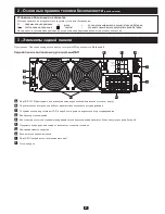
Страница 61: ... Элементы задней панели Примечание Описание контрольной панели системы ИБП приводится в Разделе 6 1 Задняя панель силового модуля системы ИБП A Порт RS 232 Примечание для использования порта необходимо извлечь сетевую карту B Переключатель настроек для работы в режиме параллельного резервирования C Соединительные порты шины CAN для работы в режиме параллельного резервирования D Вентиляторы охлажде...

Страница 62: ...свяжитесь с компанией Tripp Lite для проведения обслуживания Сохраняйте упаковку для дальнейшего использования Упаковочный лист Силовой модуль ИБП UPS 1 шт Внешний блок аккумуляторных батарей 1 шт Руководство пользователя системы ИБП 1 шт Пакет программного обеспечения для управления ИБП 1 шт Кабель RS 232 1 шт Комплект крепежа для сборки системы ИБП См ниже 1 шт Комплект крепежа для подготовки си...

Страница 63: ...nstructions see the Owner s Manual for Tripp Lite Model No BP240V10RT3U Процедура сборки в стойку с 4 опорами Rack Примечание Одна и та же процедура применяется для установки внешнего блока аккумуляторных батарей и силового модуля системы ИБП Сначала следуя приведенной ниже процедуре сборки закрепите в стойке внешний блок аккумуляторных батарей а затем в том же порядке произведите установку силово...

Страница 64: ...полняться квалифицированным электриком в строгом соответствии с основными правилами техники безопасности изложенными в настоящем Руководстве а также общими правилами и нормами электротехнической безопасности и нормативными требованиями охраны труда Неправильное подключение может привести к несчастным случаям с тяжелыми последствиями и серьезному материальному ущербу Прежде чем перейти к подключени...

Страница 65: ...ыводов 2 Пропустите провода входов выходов переменного тока через кабельные муфты и затем пропустите кабельные муфты через отверстия в крышке блока выводов A2 предварительно освободив их от заглушек Каждый входной выходной провод должен заканчиваться кольцевой клеммой 3 Подсоедините кольцевую клемму каждого входного выходного кабеля к соответствующему входному выходному выводу Затяните клеммы с кр...

Страница 66: ...ных батарей в положение OFF ВЫКЛ 2 Отвинтите винты и снимите заглушки с кабельного разъема постоянного тока силового модуля системы ИБП предназначенного для подсоединения внешнего блока аккумуляторных батарей и с кабельного разъема постоянного тока внешнего блока аккумуляторных батарей предназначенного для подсоединения силового модуля системы ИБП 3 Подсоедините концы кабеля постоянного тока C2 к ...

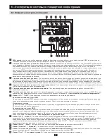
Страница 67: ...ит желтым светом при работе системы ИБП в экономичном режиме 6 Светодиодный индикатор отказа Этот красный светодиод загорается в случае сбоя или повреждения системы ИБП В случае повторного загорания после перезапуска системы ИБП обратитесь к Разделу 9 Диагностика и устранение неисправностей 7 Кнопка ON ВКЛ Данная кнопка служит для управления следующими функциями Включение питания системы ИБП Для в...

Страница 68: ...венно цифровой дисплей с символами для отображения значений температуры напряжения силы тока в амперах уровня и частоты Отображает изменяемую категорию линейное напряжение нагрузка батарея EPO Аварийное отключение питания Код Описание Er05 Низкий заряд батареи или полностью разряженная батарея Er06 Короткое замыкание на выходе Er10 Перегрузка инвертора по току Er11 Перегрев ИБП Er12 Перегрузка на ...

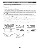
Страница 69: ...ах или ошибках означает что первый этап запуска успешно завершен и зарядное устройство начинает заряжать внешние аккумуляторные батареи 8 Нажмите кнопку ON ВКЛ и удерживайте её в течение приблизительно 3 секунд затем отпустите Вы услышите двойной звуковой сигнал после чего сообщение B на ЖК дисплее сменится сообщением C 9 Система ИБП проведет еще один сеанс самодиагностики при этом сообщение C на ...

Страница 70: ...дущий шаг 5 После завершения процедуры самодиагностики на дисплее вновь появится сообщение H Это означает что запуск в батарейном режиме успешно завершен и подключенное к системе ИБП оборудование будет работать пока заряд батарей полностью не истощится или не будут достигнуты заранее заданные параметры отключения 1 Нажмите кнопку OFF ВЫКЛ и удерживайте её в течение приблизительно 5 секунд затем от...

Страница 71: ...игнал зуммера После этого отпустите кнопки Теперь вы можете изменять любые стандартные настройки кроме настроек зуммера Q1 Q2 и самодиагностики R1 R2 при помощи кнопки Предыдущая Изменить настройку После изменения настроек нажмите кнопку ввода для сохранения изменений AA Для отмены изменений нажмите кнопку OFF ВЫКЛ и удерживайте её в этом положении в течение пяти секунд а затем отпустите BB Зуммер...

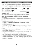
Страница 72: ...ие Одним из компонентов системы ИБП является фильтр ЭМП электромагнитных помех Для предотвращения утечки опасного для человека тока проверьте надежность заземления питающего контура переменного тока Процедура запуска 1 Разместите системы ИБП как было указано выше 2 Подсоедините кабели для параллельной связи C1 C2 к кольцевому контуру на максимальном расстоянии в 7м Закрепите кабели скобами B1 3 По...

Страница 73: ...ую карту следует удалить Закорачивание выводов EPO приводит в действие функцию EPO аварийного отключения питания которая обеспечивает аварийное отключение системы ИБП Примечание Перед использованием серийного порта RS 232 системы ИБП следует удалить сетевую карту Для подсоединения серийного порта RS 232 системы ИБП к серийному порту RS 232 компьютера используйте входящий в комплект поставки серийн...

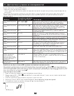
Страница 74: ...Все параметры систем ИБП работающих в режиме параллельного резервирования за исключением идентификационных номеров должны совпадать Отрегулируйте параметры Светодиодный индикатор отказа Er21 Отсоедините кабель RJ45 или задайте систему ИБП с ID 1 Светодиодный индикатор отказа Другой код ошибки Пригласите квалифицированного электрика для проверки источника питания переменного тока и проводки а затем...

Страница 75: ...БП от внешнего сетевого источника переменного напряжения Далее отсоедините все подключенное к ИБП оборудование Система ИБП должна храниться в чистом безопасном помещении при температуре не превышающей 40 С и относительной влажности не превышающей 90 без образования конденсата Примечание Если система ИБП не эксплуатируется в течение длительного времени её следует периодически включать для подзарядк...

Страница 76: ...ий В связи с этим вышеперечисленные ограничения и исключения действия настоящей гарантии могут оказаться неприменимыми в вашем конкретном случае Настоящая гарантия предоставляет вам определенные юридические права которые могут быть дополнены другими правами в зависимости от юрисдикции Tripp Lite 1111 W 35th Street Chicago IL 60609 USA ВНИМАНИЕ Перед использованием настоящего изделия каждый пользов...

Отзывы: