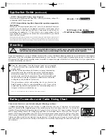
Battery Connection and Cable Sizing Chart
(continued)
Wire Gauge
2 Conductors
Watts
6
4
2
0
00
500
15 ft
25 ft
39 ft
62 ft
79 ft
700
11 ft
18 ft
28 ft
44 ft
56 ft
1000
N/R
12 ft
20 ft
31 ft
39 ft
2000
N/R
N/R
N/R
16 ft
20 ft
†
N/R = Not Recommended. NOTE: Acceptable power is directly related to cable length
(i.e. - the shorter the cable, the better the performance)
Minimum Recommended Cable
Sizing Chart
†
Always loosely twist each pair of cables together before
connecting them separately to the appropriate DC
terminal on the Inverter (positive or negative).
•
Connect Ground:
Using a #8 AWG wire or larger directly connect the Main Ground Lug to
the vehicle’s chassis or earth ground. See the Feature Identification section to locate the Main
Ground Lug on your specific Inverter model. All installations must comply with national and
local codes and ordinances.
•
Connect Fuse:
NEC (National Electrical Code) article 551 requires that you connect all of
your Inverter positive DC Terminals directly to a UL-listed fuse(s) and fuse block(s) within 18
inches of the battery. The fuse’s rating must equal or exceed the Minimum DC Fuse Rating
listed in your Inverter’s specifications. See diagrams below for proper fuse placement.
WARNING! • Failure to properly ground your Inverter to a vehi-
cle’s chassis or earth ground may result in a lethal electrical shock
hazard. • Never attempt to operate your Inverter by connecting it
directly to output from an alternator rather than a battery or battery
bank. • Observe proper polarity with all DC connections.
Vehicular
Your Inverter’s Nominal DC Input Voltage
must match
the voltage of your battery or batteries—12 Volts in most vehicular applications.
It is possible to connect your Inverter to the main battery within your vehicle’s electrical system. In most vehicles, the Inverter will be connected to one
or more dedicated auxiliary (house) batteries which are isolated from the drive system to prevent possible draining of the main battery.
12 Volt Inverter
12 Volts
12 Volts
3
5
12 Volt Main Battery Connection
12 Volt Alternator
Vehicle Battery Ground
12 Volt Main Battery
12 Volt Auxiliary (House) Battery
UL-Listed Fuse & Fuse Block (mounted
within 18 inches of the battery)
Battery Isolator
Large Diameter Cabling, Maximum 00 Gauge to Fit Terminals
8 AWG (minimum) Ground Wire
8
7
6
5
4
3
2
1
12 Volt Inverter
12 Volts
12 Volts
12 Volts
12 Volt Main and Auxiliary (House) Battery
Connection (Isolated Parallel)
1
4
1
7
6
2
2
5
7
3
2
8
8
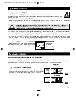
AC Output Connection
To avoid overloading your Inverter, be sure to match the power requirements of the equipment you plan to run at any one time (add their total
watts) with the output wattage capacity of your Inverter model. When figuring the power requirements of your equipment, do not confuse
"continuous" wattage with "peak" wattage ratings. Most electric motors require extra power at start-up ("peak" wattage) than required to run
continuously after start-up, sometimes over 100% more. Some motors, such as in refrigerators and pumps, start and stop intermittently
according to demand, requiring "peak" wattage at multiple, unpredictable times during operation.
•
DoubleBoost
™
Feature
: Tripp Lite Inverters deliver up to twice their nameplate rated wattage for up to 10 seconds,* providing the extra
power needed to cold start heavy-duty tools and equipment.
• OverPower
™
Feature:
Tripp Lite Inverters deliver up to 150% of their name plate rated wattage for up to 1 hour,* providing plenty
of reserve power to reliably support tools and equipment longer.
* Actual duration depends on battery age, battery charge level and ambient temperature.
7
200702194 PowerVerter DC-AC Owner’s Manual CH.qxd 2/23/2007 4:02 PM Page 7

