6
6
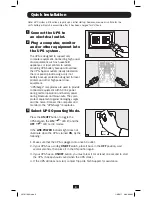
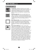
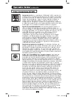
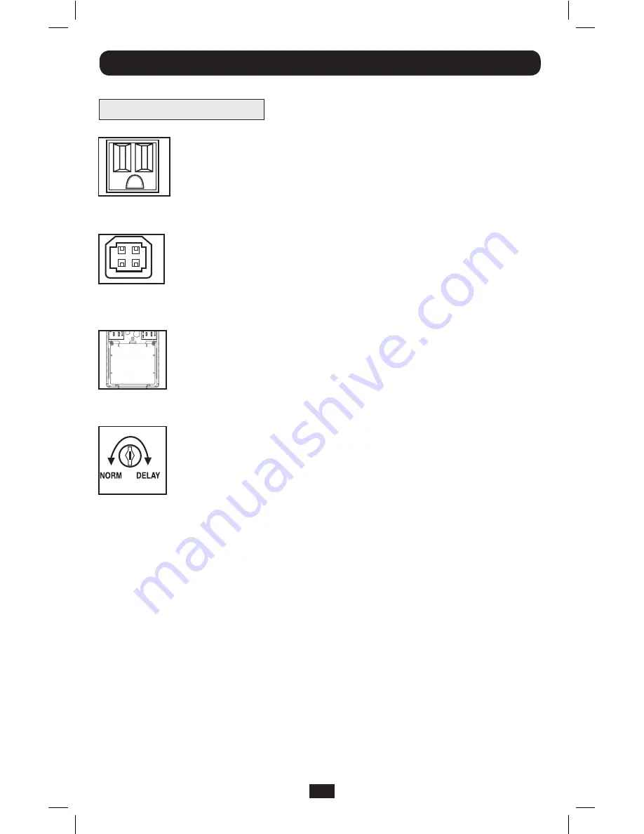
AC Receptacles:
“UPS/Surge” receptacles are used to provide
connected equipment with AC line power during normal operation and
battery power during blackouts and brownouts. They also protect
equipment against damaging surges and line noise. “Surge-Only”
receptacles are used to provide peripherals with surge protection
without committing precious battery power to support them during
blackouts.
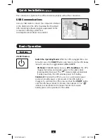
USB Communication Port:
This port can connect the UPS to any
computer for automatic file saves and unattended shutdown in the
event of a power failure. Use with Tripp Lite's PowerAlert Software and
USB cable. A USB cable is included with the UPS. PowerAlert Software
is available FREE via the Web at www.tripplite.com/software/. NOTE: This
connection is optional. The UPS will work properly without this
connection.
Battery Replacement Door:
Under normal conditions, the original
battery in the UPS will last several years. Battery replacement should be
performed only by qualified service personnel. Refer to “Battery
Warnings” in the Safety section. Should the UPS require battery
replacement, visit Tripp Lite on the Web at www.tripplite.com/support/
battery/index.cfm to locate the specific replacement battery for the
UPS.
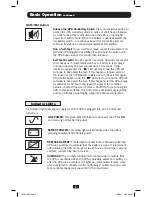
Power Sensitivity Adjustment:
This dial is normally set fully
counterclockwise, which enables the UPS to protect against waveform
distortions in its AC input. When such distortions occur, the UPS will
normally switch to providing sine wave power from its battery reserves
for as long as the distortions are present. In some areas with poor
utility power or where the UPS’s input power comes from a backup
generator, frequent brownouts and/or chronic waveform distortion could
cause the UPS to switch to battery too often, draining its battery
reserves. It may be possible to reduce how often the UPS switches to
battery due to waveform distortion or brownouts by experimenting with
different settings for this dial. As the dial is turned clockwise, the UPS
becomes more tolerant of variations in its input power’s AC waveform
and switches to battery less often. NOTE: The further the dial is
adjusted clockwise, the greater the degree of waveform distortion the
UPS will allow to pass to connected equipment. When experimenting
with different settings for this dial, operate connected equipment in a
safe test mode so that the effect on the equipment of any waveform
distortions in the UPS’s output can be evaluated without disrupting
critical operations. The experiment should last long enough to assure
that all expected line conditions are encountered.
Basic Operation
continued
Other UPS Features
201011083.indb 6
1/6/2011 9:00:19 AM


