Version 3.2
Page: 45
followed by the nuts to hold the board in place. You can also do the reverse and screw the bolt
through the board, stand-off and finally into the chassis without the need for a nut.
Connecting the Board
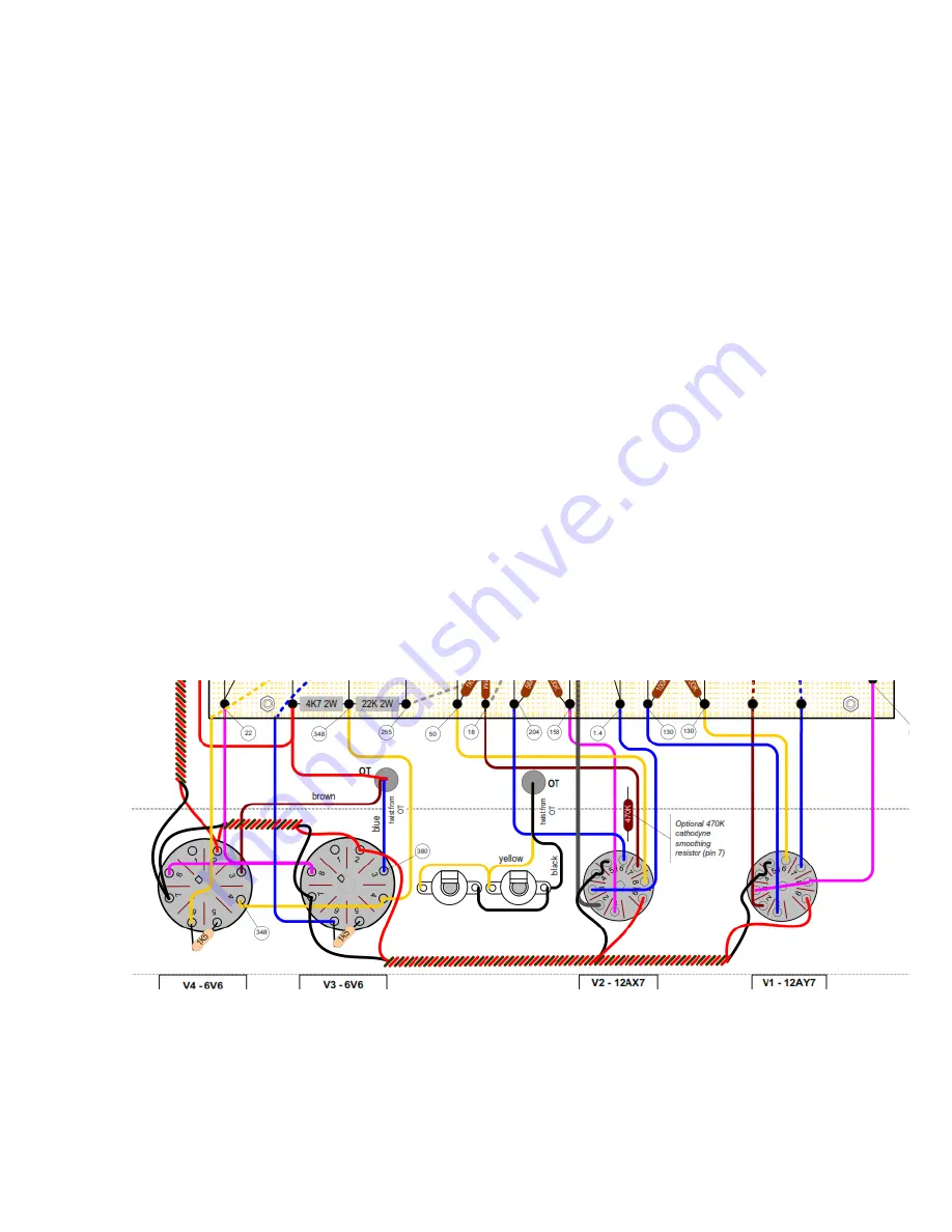
Now is the time to make the connections from the eyelet board to the tubes and
potentiometers.
Tip: On a copy of the layout, highlight the connections as you complete them to make sure
they are done correctly.
1. Connect and solder the power wire from the standby switch to the board.
2. Connect and solder the Output Transformer Red centre tap to the B+ on the board
(optionally route it back to the stand-by switch).
3. Connect and solder the ground wire from the ground side of the 250 ohm /25uF power
tube cathode resistor pair to the Power Ground.
4. Connect and solder the ground wire from the ground side of the 820 ohm /25uF preamp
tube cathode resistor pair to the Pre-Amp Ground.
Then start at one end of the board and work your way sequentially around the board doing the
point-to-point wiring with the flying leads to tube sockets. Board to tube pin; board to tube
pin etc. Start at V1, pin 1 and move to the far end of the board to V4.
Connect Board to Potentiometers
The easiest way to wire these correctly is to carefully follow the layout, and do one terminal
connection at a time.
Содержание Trinity Tweed Amp
Страница 2: ...Version 3 2 Page 2 ...
Страница 16: ......
Страница 20: ...Version 3 2 Page 20 Input Jack Theory from 18watt com ...
Страница 25: ...Version 3 2 Page 25 ...
Страница 49: ...Version 3 2 Page 49 ...
Страница 65: ...Version 3 2 Page 65 HEYBOER OT for TWEED 6L6GT CONVERSION ...
Страница 66: ...Version 3 2 Page 66 ...
Страница 75: ...Version 3 2 Page 75 ...
Страница 76: ...Version 3 2 Page 76 ...
Страница 77: ...Version 3 2 Page 77 Trinity Amps Schematics and Layouts ...

