Trinamic TMC603-EVAL Скачать руководство пользователя страница 1


TRINAMIC

®

 Motion Control GmbH & Co. KG 

Sternstraße 67 

– 20357 Hamburg 

GERMANY 

www.trinamic.com 


1  Features 

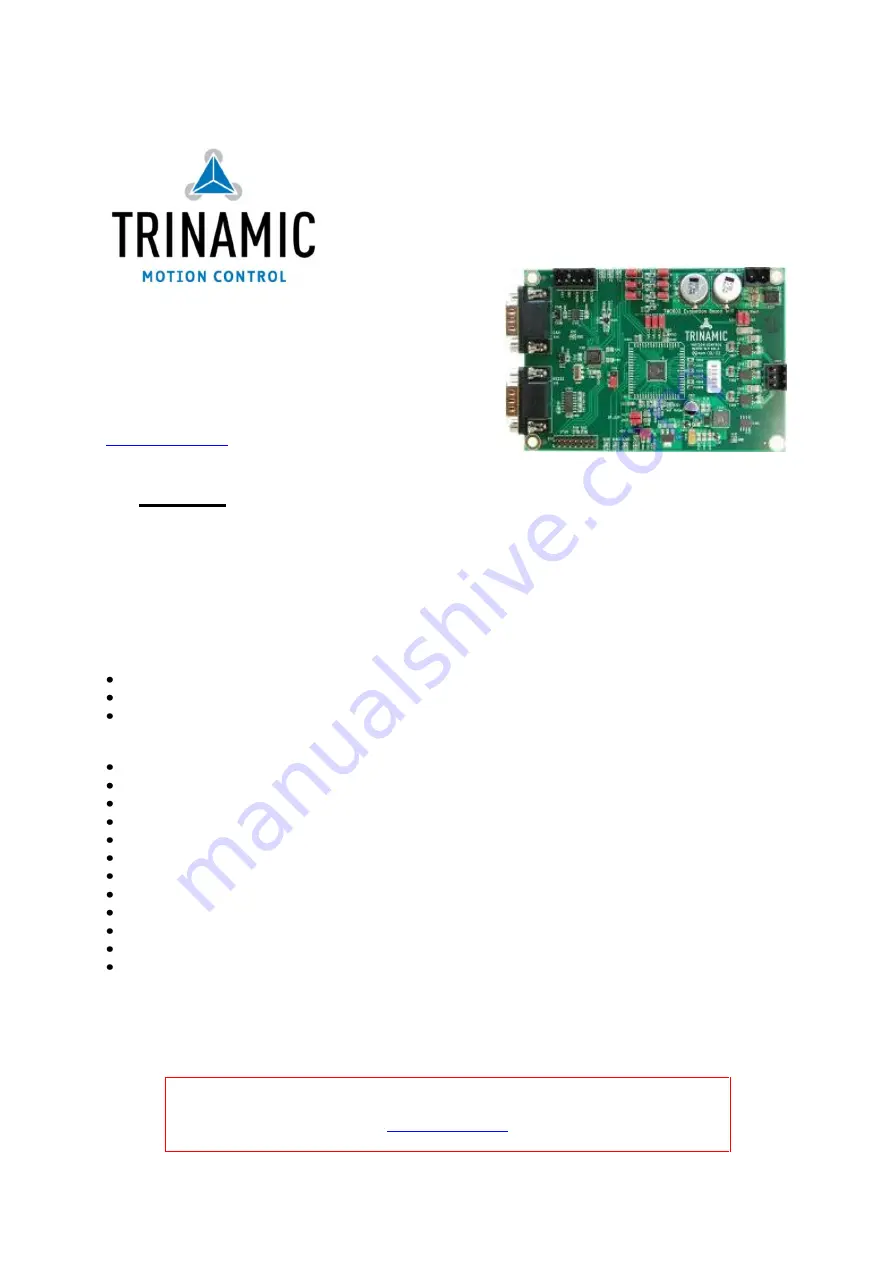
The TMC603 evaluation board makes it possible to evaluate the features of the TMC603 three phase 
BLDC motor driver with 

back EMF commutation hallFX™. On the evaluation board the Infineon XC886 

microcontroller  is  used  to  control  the  TMC603.  The  microcontroller’s  FLASH  memory  contains  a 
program  which  configures  the  TMC603  and  controls  the  communication  with  the  PC  via  the  CAN 
interface or the RS232 interface. To use the CAN interface the TRINAMIC USB-2-X is available as an 
USB  adapter.  Windows  based  PC  software  allows  tuning  of  all  operation  parameters  for  every  three 
phase BLDC motor. 


Motor type 


3 phase BLDC motor  


block commutation  


Rotor position feedback: sensorless or hall sensor 


Highlights 


Up to 6A (I

RMS

) nominal motor current 


12V to 48V operating voltage  


Integrated current measurement using power MOS transistor RDSon  


hallFX™ sensorless back EMF commutation emulates hall sensors  


Integrated Break-before-Make logic: No special microcontroller PWM hardware required  


EMV optimized current controlled gate drivers 

– up to 150mA possible  


Overcurrent / Short to GND and undervoltage protection and diagnostics integrated  


Internal QGD protection: Supports latest generation of Power MOSFETs  


Integrated supply concept: Step down switching regulator 


Common rail charge pump allows for 100% PWM duty cycle  


Communication to the PC via CAN interface and RS232 interface 


Firmware update via RS232 interface 


Please check our website for the latest version of manual and firmware! 

www.trinamic.com


TMC603EVAL 

– MANUAL 

Evaluation  board  for  the  TMC603  three  phase 
motor driver with BLDC back EMF commutation 
hallFX™ 

Содержание TMC603-EVAL

Страница 1: ...on feedback sensorless or hall sensor Highlights Up to 6A IRMS nominal motor current 12V to 48V operating voltage Integrated current measurement using power MOS transistor RDSon hallFX sensorless back...

Страница 2: ...quipment intended to support or sustain life and whose failure to perform when properly used in accordance with instructions provided can be reasonably expected to result in personal injury or death T...

Страница 3: ...on via RS232 interface 15 6 2 2 Connection via CAN interface 15 6 3 SELECTING THE OPERATING MODE 15 6 3 1 The operating mode Block HallFX Open Loop 15 6 3 2 The operating mode Block HallFX Closed Loop...

Страница 4: ...motor N S TMC603 micro controller POWER BUS IO position sensor Figure 1 The structure of the TMC603 evaluation board The TMC603 is a BLDC driver IC using external power MOS transistors Its unique feat...

Страница 5: ...to or disconnected from the evaluation board while the board is disconnected from power supply as otherwise the evaluation board could get damaged Figure 2 Default settings of jumpers for quick start...

Страница 6: ...2500rpm and the speed control time Speed Ctl Time The speed control time is a time duration in ms In this time the PWM duty cycle counts up or down by a value of 1 16 You can change these parameters...

Страница 7: ...s the current value for startup Current Time ms is the regulation time of the current controller Current Control Kp is the proportional gain of the controller Speed Ref rpm is the reference to change...

Страница 8: ...he pins marked INPUT1 INPUT2 and INPUT3 CAN X115 This Sub D connector is a CAN interface for communication to the PC Additionally you need a Trinamic USB 2 X interface converter which allows easy inte...

Страница 9: ...eds 5V power supply This jumper allows to select the 5V power source You have two options 1 Integrated 5V linear regulator of the TMC603 40 mA cont jumper plugged in pin 2 and pin 3 2 External voltage...

Страница 10: ...ns 1 current measurement output CUR3 of the TMC603 jumper plugged in pin 1 and pin 2 2 shunt based current measurement with a difference amplifier jumper plugged in pin 2 and pin 3 The default option...

Страница 11: ...or is occurred by undervoltage of VLS or VCP as well as by short to ground of the power MOS half bridges 5 4 Dimensions The mechanical dimensions of the TMC603 evaluation board are shown in Figure 5 p...

Страница 12: ...currently three modes 1 Block HallFX Open Loop This mode is the sensorless block commutation with hallFX and open loop current control In this mode the motor will start with block commutation by usin...

Страница 13: ...t of the motor Please take into account that the unit of the BEMF constant is in rpm V Pole pairs This is the number of pole pairs of the motor Motor Startup Here you can enter the parameters for moto...

Страница 14: ...the speed control is disabled the duty cycle reference value defines the actual PWM duty cycle Enable speed control If this option is selected the speed control is enabled You can disable the speed co...

Страница 15: ...6 3 Selecting the operating mode If the connection is established you can select the operating mode by pressing the pull down menu The several modes are Block HallFX Open Loop Block HallFX Closed Loop...

Страница 16: ...st parameter is the resistance of the motor coils The second parameter is the maximum current This is the peak current of the motor The last parameters are the pole pair number and the BEMF constant o...

Страница 17: ...y cycle counts up or down by a value of 1 16 You can change these parameters at any time Please keep in mind to press the Set button Figure 12 Current control options Thereafter press the Start button...

Страница 18: ...described in chapter 6 4 2 to initialize the sine startup If the motor is running then stop the motor by pressing the Stop button Thereafter select the operating mode Sine HallFX Closed Loop and star...

Страница 19: ...efined speed reference value Speed Ref In this example the speed reference value is set to 3000rpm The PWM duty cycle is about 62 dependent on the mechanical load Now we would like to disable the spee...

Страница 20: ...tion for sine startup is not required if you have already started the motor with the same settings in operating mode Block HallFX Closed Loop Figure 15 Parameter settings for open loop current control...

Страница 21: ...e Set buttons Then press the Start button and the motor accelerate up to the defined speed reference value Speed Ref In addition you can select the chopper mode Three chopper modes are available Low s...

Страница 22: ...e used Set the baud rate to 115200 baud The module address is 1 Now open the install OS window Figure 18 At first load the new firmware file by pressing the Load button The file is then checked if it...

Страница 23: ...rol Example QMot QBL4208 41 04 006 19 Figure 15 Parameter settings for open loop current control Example QMot QBL4208 41 04 006 20 Figure 16 Parameter settings for hall sensors Example QMot QBL4208 41...

Страница 24: ...W PWM duty cycle limited in hallFX mode 1 03 05 Mrz 09 MW Error in the current regulation resolved 1 04 03 Apr 09 MW Sinusoidal commutation ramp up added Option Enable Speed Control added Table 8 Firm...

Страница 25: ...asurement signals The shunt resistor R301 will also have an effect on the current measurement although the shunt resistor is bypassed by the jumpers X302 and X303 If you use one of the first evaluatio...

Отзывы: