background image

Purpose of contacts 

Contact 

Description 

+E 

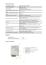
Power  terminal 

COM 

Power supply – terminal and common terminal for IN1, IN2 inputs 

IN1 ir IN2 

Terminals for input circuits  


2 unused terminals 

NC 

Output relay NC terminal 

Output relay common C terminal 

NO 

Output relay NO terminal 

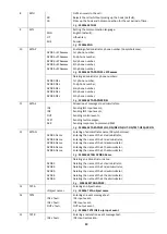
Light indication 

Indicator 

Status 

Description 

NETWORK 
(denotes 
communication 
between the 
controller and 
GSM network)


OFF


Controller 

G14

 initialisation in progress


Yellow flashing  

Registration to GSM network in progress


Green light (5 sec.) + N 
green flashes  
 

N - relative GSM signal level. 
3 flashes – minimum sufficient level (30%),  
10 flashes – maximum (100%). 

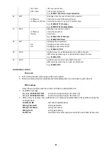
TROUBLE 
(denotes 
controller 
operation) 

OFF 

No faults 

Green light 

Programming mode 

Red light (5 sec.) + red 
flashes: 


1 flash 

Insufficient power supply voltage, below 9 V 

2 flashes 

No SIM card 

3 flashes 

PIN code error 

4 flashes 

Registration to GSM network failed for 60 seconds 

5 flashes 

Operation mode setting error * 

6 flashes 

Threshold GSM signal level (~ 30%)** 

7 flashes 

Critical error in the parameters structure  

8 flashes 

Error in the user phone number list structure 

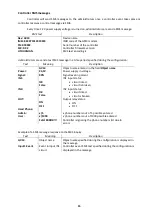
POWER  
(denotes 
controller 
power supply) 

OFF 

No power supply 

Green light 

Normal power supply  

Yellow light 

Low supply voltage, below 11,5V 

Yellow flashing 

Insufficient power supply voltage, below 9 V 

Notes: 

*   - not a single administrator phone number is entered and the user list is prohibited. 
**   - use a portable GSM antenna with a cable and fit it to the exterior of the case if 
controller is mounted into the metal case of automatics.


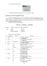
Controller installation 

Follow this controller installation procedure in order to ensure that controller will be available 

for use to everyone with whom SIM card phone number is shared.  

1.


Purchase controller 

GV14

. Factory settings should not be changed! 

2.


Insert the SIM card of the desired network provider into the controller.  

-


It is not recommended to use pre-paid contract SIM cards. 

-


SIM card PIN code must be disabled.  

-


SIM card must be already registered in the network.  

3.


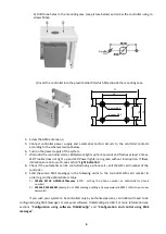
Embed the controller into the automatics mounting case.  

a) Use adhesive mounting tape to mount the controller inside of the case.  

Содержание GV14

Страница 1: ...CONTROLLER GV14 User Manual Draugystes g 17 LT 51229 Kaunas E mail info trikdis lt www trikdis lt...

Страница 2: ...Controller installation 5 Wiring diagrams 7 Configuration using software TrikdisConfig 7 Connecting to a computer 7 Configuration of controller operation 8 User list 9 Administrator list 10 Recording...

Страница 3: ...st c mode Administrator controller output relay contacts may be switched by those whose phone number is on the administrator list Memory of 5 administrator and 1000 user names and their phone numbers...

Страница 4: ...command e g next phone call Memory Up to 5 administrator names and their phone numbers Up to 1000 user names and their phone numbers Inputs 2 IN1 and IN2 Set for NO resistance 10 k or NC resistance 0...

Страница 5: ...SM signal level 30 7 flashes Critical error in the parameters structure 8 flashes Error in the user phone number list structure POWER denotes controller power supply OFF No power supply Green light No...

Страница 6: ...t interruption If these indications are not as such see section Light indication 8 Check if the automatics can be controlled using a phone call call the SIM card number of the controller 9 Send these...

Страница 7: ...rameters are set using computer software TrikdisConfig Software may be found on www trikdis lt Connecting to a computer 1 Connect the controller to the computer USB slot using a USB cable e g USB type...

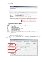
Страница 8: ...atus Done is displayed after every successful reading or saving action GV14 Product name SN Controller serial number BL Controller firmware boot loader version FW Controller firmware version HW Contro...

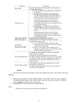
Страница 9: ...eration mode a Level relay contacts status is switched to other command status e g other phone call once controller receives a control command b Impulse relay contacts status is switched to the opposi...

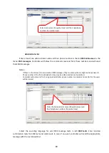
Страница 10: ...rst administrator may only be edited and cannot be deleted Controller will not work if not a single administrator phone number is entered and control for the users will be denied Select the encoding l...

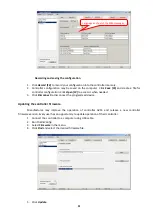
Страница 11: ...3 Click Disconnect to disconnect the programmed device Updating the controller firmware Manufacturer may improve the operation of controller GV14 and release a new controller firmware version Every u...

Страница 12: ...3456 password SETAP command APNR1 37068700000 parameters Commands sent in SMS messages No Command Contents Description 1 RESET Resetting controller GV14 E g 123456 RESET 2 INFO Inquiring about the con...

Страница 13: ...events Sending test messages Sending responses to command SMS E g 123456 SETAE APNR1 IN1 ON IN2 ON OUT ON TEST OFF ACK ON 12 SETAN APNR1 Name APNR2 Name APNR3 Name APNR4 Name APNR5 Name Entering of a...

Страница 14: ...trator list will be sent E g 123456 LISTA 20 LISTU An SMS query for a User list in SMS to be sent SMS message containing of a User list will be sent E g 123456 LISTU Automatics control Phone call 1 Ca...

Страница 15: ...GV14 Object name entered in the field Object name Power 24 5V Power supply in voltage Signal 90 Signal level in percent IN1 OK False IN1 input status circuit intact circuit is broken IN2 OK False IN2...

Страница 16: ...ce known to the maintenance specialists Device is disconnected from the electrical network by turning off the automatic fuse Warranty and limitation of liability The manufacturer provides a 24 month w...

Отзывы: