


Page 25
www.tri-m.com
TCB1000 Series User Guide Rev A
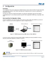
3 Configuration
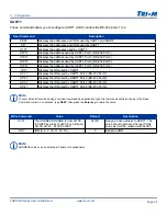
Read Command
Description
UCD?
Displays the value of the divider for the UART Clock.
Write Command
Value
Default
Description
UCD=
F or S
F
UART clock divider setting
F=FAST (14.7456MHz), S=SLOW (1.8432MHz)
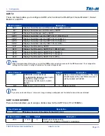
Read Command
Description
SER?
Displays the addresses and IRQs used by UART1 and UART2.
U2?
Displays the addresses and IRQ used by UART2.
U2P?
Displays the addresses used by UART2.
U2P1?
Displays the address used by UART2 Port 1 (RS-485 port).
U2P2?
Displays the address used by UART2 Port 2 (Socket 1).
U2P3?
Displays the address used by UART2 Port 3 (Socket 2.)
U2P4?
Displays the address used by UART1 Port 4 (CPU).
U2I?
Displays the IRQ used by UART2.
U2I1?
Displays the IRQ used by UART2 Port 1 (RS-485 port).
U2I2?
Displays the IRQ used by UART2 Port 2 (Socket 1).
U2I3?
Displays the IRQ used by UART2 Port 3 (Socket 2).
U2I4?
Displays the IRQ used by UART1 Port 4 (CPU).
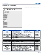
UART 2
These commands allow you to configure UART2, which controls the RS-485 port, Socket Modem 1, Socket
Modem 2, and CPU.
UART CLOCK DIVIDER
These commands allows you to assign a divider value for the UART Clock (f=14.7456MHz).
Note
Write Commands take effect when you enter the
UPD
command and are saved with the
STD
command. The configuration
settings are then saved to config.txt located on the mass storage device.
Write Command
Value
Default
Description
U2P=
ADDRESS (in Hexadecimal)
The ADDRESS RANGE is from 0x200
to 0x3E0 by steps of 0x20.
For instance, 0x100, 0x120…0x3C0,
0x3E0.
0x200
Assign a base address to UART2. The value
should represent the real 10bits value as it
will be masked with 0x3E0.
U2I=
IRQ (5, 6, 7, 10, 11, 12, 15)
5
Assign an IRQ.
Note
If you enter an invalid Value, a ‘value out or range’ message will appear and the default value will be used instead.